System Overview 2-11
No. Symbol Function
<1>
<2>
USB port, used for connecting USB devices
Parallel port, connects the parallel port devices,
reserved.
<3>
Unavailable to the user.
<4>
Ethernet interface (<3> is reserved for future use).
<5>
Remote interface for connecting video printer
<6>
Serial port; connects the serial port devices.
<7>
VGA signal output; connects a monitor or projector.
<8>
DVI Out
DVI signal output
<9>
Reserved port (Separate video input)
<10>
Separate video output
<11>
Reserved port (Composite video input)
<12>
Composite video output.
<13><14>
Reserved port (Audio input)
<15><16>
Audio output.
<17>
Malfunction
indication lights
Indicate the system’s malfunction
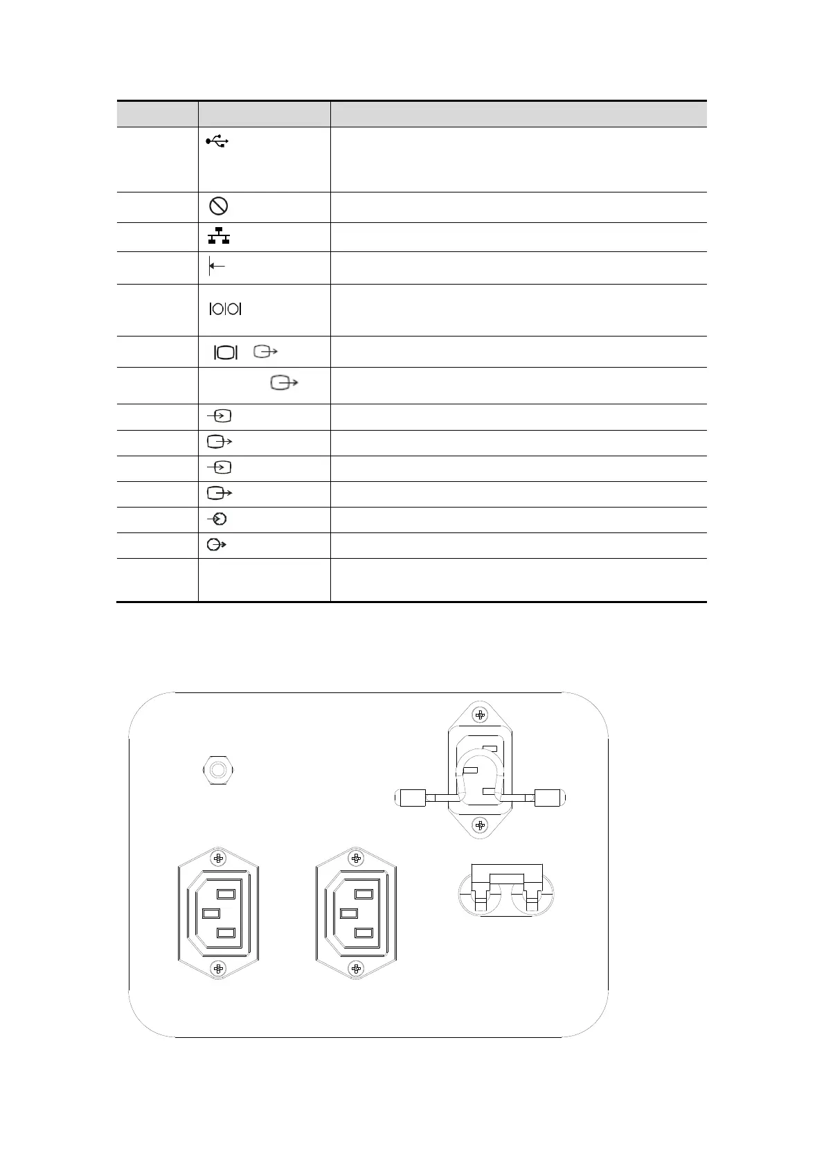
2.8 Power Supply Panel
<1>
<2>
<3> <4>
<5>