18. Interface specifications
MiR600 User Guide (en) 08/2021 - v.1.0 ©Copyright 2021: Mobile Industrial Robots A/S. 219
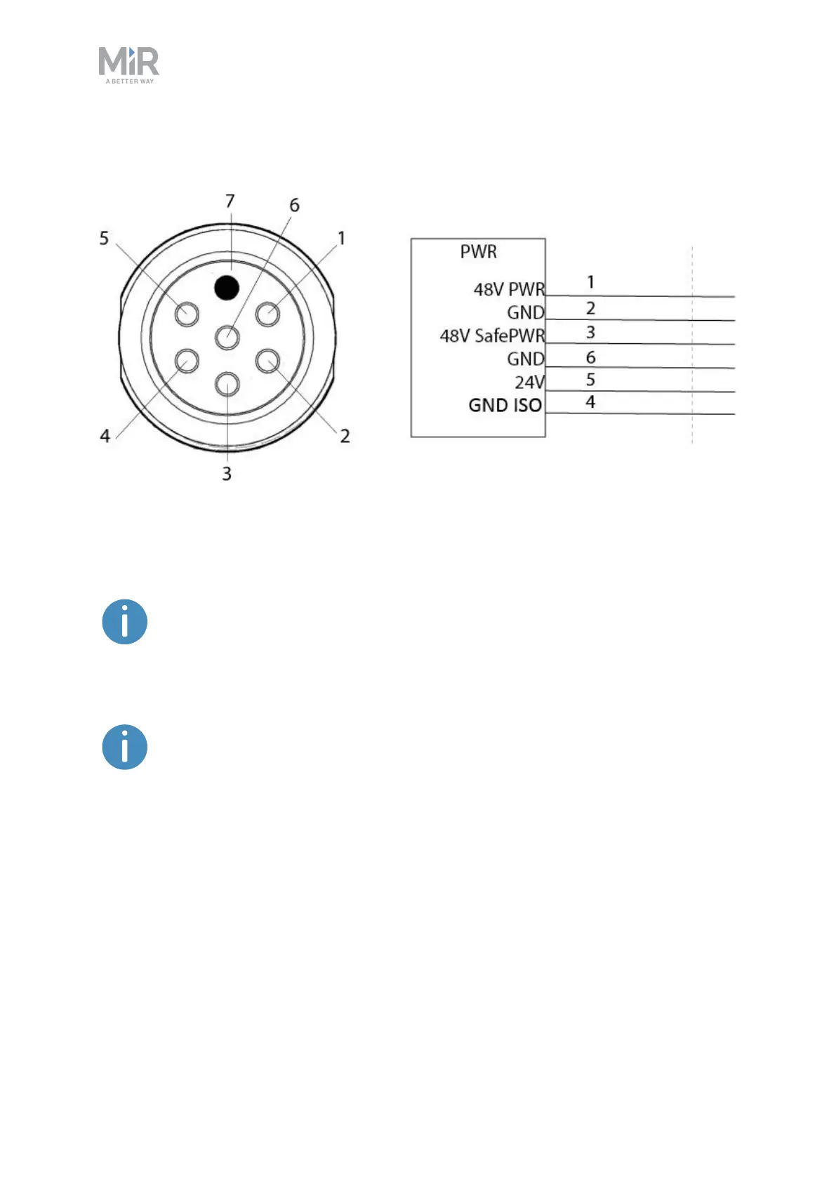
Power
Figure 18.1. Pin numbers: female connector viewed from the front (left) and wiring diagram (right).
Table 18.1 contains the description of the pins of the Power interface.
The maximum current across pins 1 and 3 combined is 20A when the robot is
at standstill. When the robot is driving, the maximum combined current is 2A.
The maximum capacitance of devices connected to pins 1 and 3 is 2000 µF
combined. If your device has a higher capacitance, you must integrate your
own softstarter that keeps the current under 2 A for the first 100 ms, and
thereafter under 20A with a maximum peak current of 100A.