18. Interface specifications
MiR600 User Guide (en) 08/2021 - v.1.0 ©Copyright 2021: Mobile Industrial Robots A/S. 226
Table 18.3 contains the description of the pins of the Ethernet interface.
Pin number Signal name
1 TX+
2 RX+
3 TX-
4 RX-
Table 18.3.
Description of the pins in the Ethernet interface
18.2 Right compartment interfaces
This section describes the safety interfaces and antenna interface located in the right side
top compartment of MiR600.
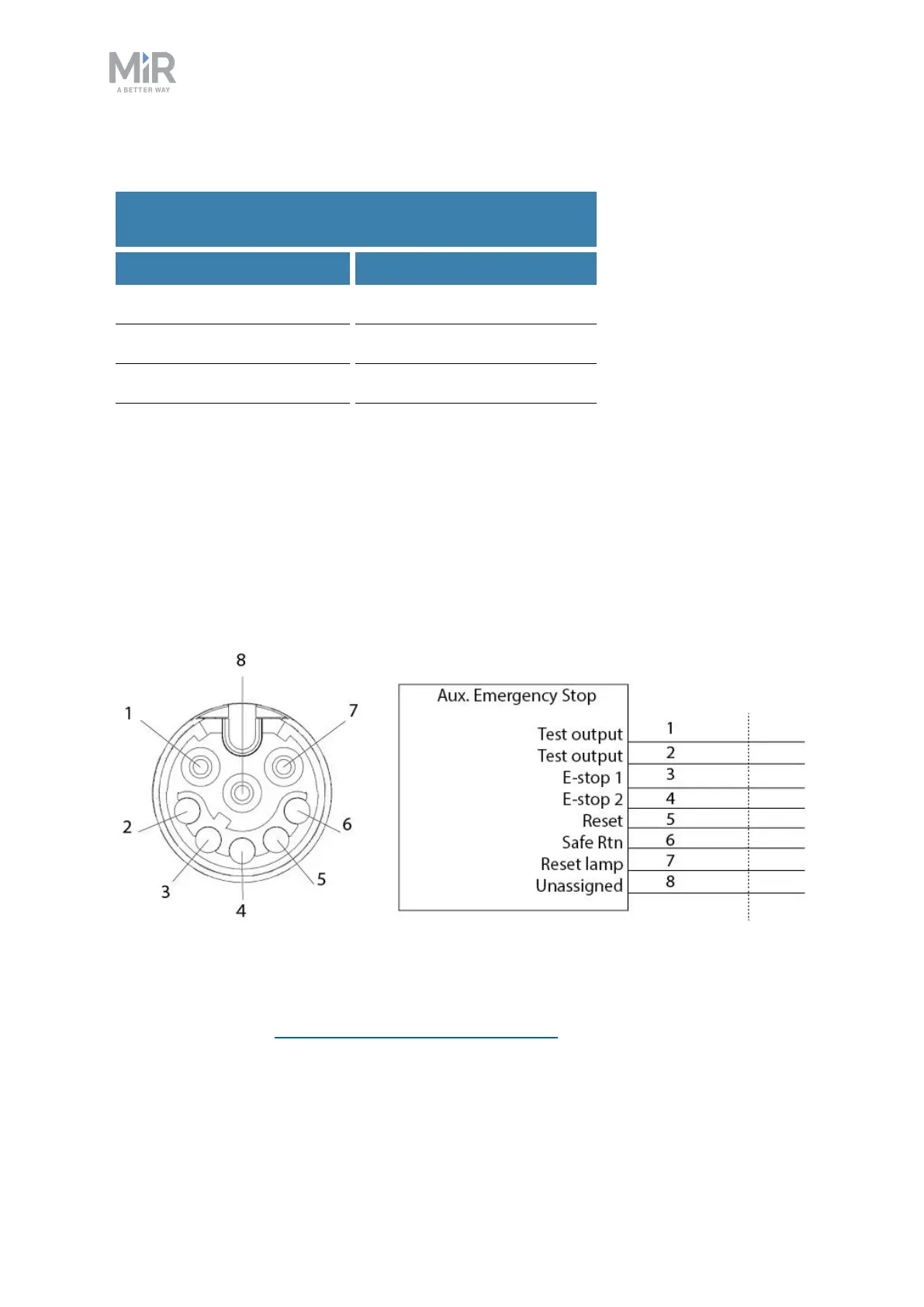
Auxiliary emergency stop
Figure 18.6. Pin numbers: female connector viewed from the front (left) and wiring diagram (right).
The Auxiliary emergency stop interface is designed to support Emergency stop and other
safety functions—see Emergency stop circuit on page110.