90
5 SYSTEM CONFIGURATION
5.2 Structure of CC-Link IE TSN Class B/A Devices (CC-Link IE TSN Protocol Version 2.0 Only) and Ethernet Devices
Structure of modules on CC-Link IE TSN and Ethernet devices
Connection with modules on CC-Link IE TSN and Ethernet devices
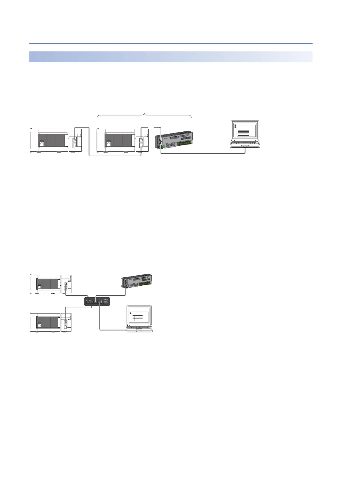
Line topology
The network with modules and devices is configured in a line topology. An industrial switch (for CC-Link IE TSN Class A) is
not required.
Up to eight modules on CC-Link IE TSN can be connected to P1 or P2 of the master station at the position indicated with (1).
Connect Ethernet devices to the end of the network.
When an error occurs in a device station, the stations connected after the faulty station will be disconnected.
Star topology
Modules or devices are connected in a star topology via an industrial switch.
• Since cyclic data is sent to an Ethernet device when "Communication Mode" is set to "Multicast" and a local station is used
with an Ethernet device on the end side via an industrial switch, communication may not be possible depending on the type
of Ethernet device. The communication will be enabled by configuring settings with the industrial switch so that the
multicast frame (with multicast MAC address 09:00:70:00:10:02 and 09:00:70:00:10:05) will not be transferred to the port of
the Ethernet device.
No.0: Master station
No.1: Local station (1st device)
No.8: Remote station (8th device)
(2) Ethernet device
Class A: CC-Link IE TSN Class A device
Class B: CC-Link IE TSN Class B device
No.0: Master station
No.1: Local station
No.2: Remote station
(1) Ethernet device
Class A: CC-Link IE TSN Class A device
Class B: CC-Link IE TSN Class B device
No.0
Class B
No.1
Class B
No.8
Class A
(2)
(1)
......
No.0
Class B
No.1
Class B
(1)
No.2
Class A
Industrial switch
(for CC-Link IE TSN
Class B)

 Loading...


