101
Selection and protection of a motor
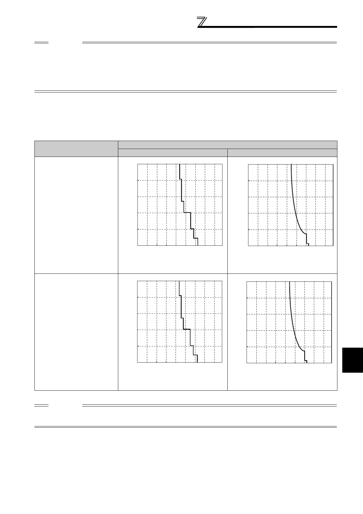
(2) Electronic thermal relay function operation characteristic (THT)
Electronic thermal relay function (transistor protection thermal) operation characteristics of the inverter when the ratio
of the motor current to the inverter rated current is presented as transverse is shown. Transverse is calculated as
follows: (motor current [A]/inverter rated current [A]) 100 [%].
CAUTION
Protective function by electronic thermal relay function is reset by inverter power reset and reset signal input. Avoid
unnecessary reset and power-OFF.
When using multiple motors with one inverter, or using a multi-pole motor or a specialized motor, provide an external thermal
relay (OCR) between the inverter and motor. And for the setting of the thermal relay, add the line-to line leakage current (refer
to page 40) to the current value on the motor rating plate. For low-speed operation where the cooling capability of the motor
reduces, it is recommended to use a thermal protector or thermistor-incorporated motor.
When the difference between the inverter and motor capacities is large and the setting is small, the protective characteristics of
the electronic thermal relay function will be deteriorated. In this case, use an external thermal relay.
Optimum Conditions
Inverter Capacity
FR-F740-01160 or less FR-F740-01800 or more
Running frequency : 1Hz or more
Carrier frequency: 2kHz
Running frequency : 1Hz or less
Carrier frequency: 2kHz
CAUTION
Protective function by electronic thermal relay function is reset by inverter power reset and reset signal input. Avoid
unnecessary reset and power-OFF.
The operation time of the transistor protection thermal relay shortens when the Pr. 72 PWM frequency selection setting increases
0
30
60
90
120
150
0 25 50 75 100 125 150 175 200
Ratio of the motor current
to the inverter rated current (%)
Operation time (S)
0
30
60
90
120
150
0 25 50 75 100 125 150 175 200
Ratio of the motor current
to the inverter rated current (%)
Operation time (S)
0
3
6
9
12
15
0 25 50 75 100 125 150 175 200
Ratio of the motor current
to the inverter rated current (%)
Operation time (S)
0
3
6
9
12
15
0 25 50 75 100 125 150 175 200
Ratio of the motor current
to the inverter rated current (%)
Operation time (S)

 Loading...


