74
Adjustment of the output torque (current) of the motor
4.3.4 Stall prevention operation
(Pr. 22, Pr. 23, Pr. 48, Pr. 49, Pr. 66, Pr. 148, Pr. 149, Pr. 154, Pr. 156, Pr. 157)
The above parameters can be set when Pr. 160 User group read selection = "0". (Refer to page 185)
*1 This parameter allows its setting to be changed during operation in any operation mode even if "0 (initial value) or 1" is set in Pr. 77 Parameter write
selection.
*2 When Pr. 570 Multiple rating setting = "1", performing inverter reset and all parameter clear changes the initial value and setting range. (Refer to
page 79)
This function monitors the output current and automatically changes the output frequency to prevent the inverter
from coming to trip due to overcurrent, overvoltage, etc. It can also limit stall prevention and fast-response
current limit operation during acceleration/deceleration, driving or regeneration.
Stall prevention
If the output current exceeds the stall prevention operation level, the output frequency of the inverter is
automatically varied to reduce the output current.
Also the second stall prevention function can restrict the output frequency range in which the stall prevention
function is valid.
Fast-response current limit
If the current exceeds the limit value, the output of the inverter is shut off to prevent an overcurrent.
Parameter
Number
Name Initial Value
Setting
Range
Description
22 *1
Stall prevention operation
level
110%
*2
0 Stall prevention operation selection becomes invalid.
0.1 to 120%
*2
Set the current value at which stall prevention
operation will be started.
9999 Analog variable
23
Stall prevention operation
level compensation factor
at double speed
9999
0 to 150%
*2
The stall operation level can be reduced when
operating at a high speed above the rated frequency.
9999 Constant according to Pr. 22
48
Second stall prevention
operation current
110%
*2
0 Second stall prevention operation invalid
0.1 to 120%
*2
The second stall prevention operation level can be
set.
49
Second stall prevention
operation frequency
0Hz
0 Second stall prevention operation invalid
0.01 to 400Hz
Set the frequency at which stall prevention operation
of Pr. 48 is started.
9999 Pr. 48 is valid when the RT signal is ON.
66
Stall prevention operation
reduction starting frequency
50Hz 0 to 400Hz
Set the frequency at which the stall operation level is
started to reduce.
148
Stall prevention level at 0V
input
110%
*2 0 to 120% *2
Stall prevention operation level can be changed by
the analog signal input to terminal 1.
149
Stall prevention level at
10V input
120%
*2 0 to 120% *2
154
Voltage reduction
selection during stall
prevention operation
1
0
With voltage
reduction
You can select whether to use
output voltage reduction
during stall prevention
operation or not.
1
Without voltage
reduction
156
Stall prevention operation
selection
0
0 to 31,
100, 101
You can select whether stall prevention operation and
fast-response current limit operation will be performed
or not.
157 OL signal output timer 0s
0 to 25s
Set the output start time of the OL signal output when
stall prevention is activated.
9999 Without the OL signal output
(1) Setting of stall prevention operation level (Pr. 22)
Set in Pr. 22 the ratio of the output current to the rated inverter current at
which stall prevention operation will be performed. Normally set 110%
(initial value).
Stall prevention operation stops acceleration (makes deceleration) during
acceleration, makes deceleration during constant speed, and stops
deceleration during deceleration.
When stall prevention operation is performed, the OL signal is output.
CAUTION
If an overload status lasts long, an inverter trip (e.g. electronic thermal relay function (E.THM)) may occur.
When Pr. 156 has been set to activate the fast-response current limit (initial setting), the Pr. 22 setting should not be higher than
140%. The torque will not be developed by doing so. (When Pr. 570 = "1")
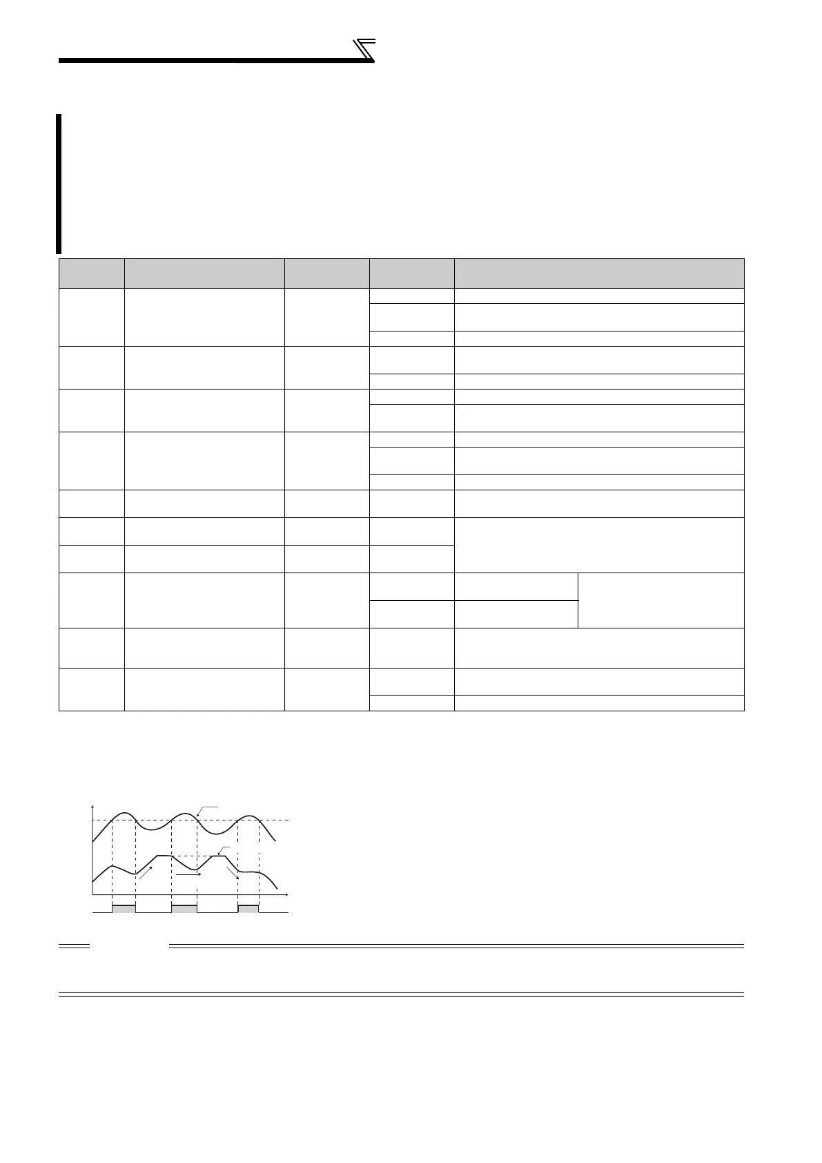
Stall prevention operation example
Pr.22
OL
Output current
Output frequency
Acceleration
Constant
speed
Deceleration
Time

 Loading...


