275
PID control
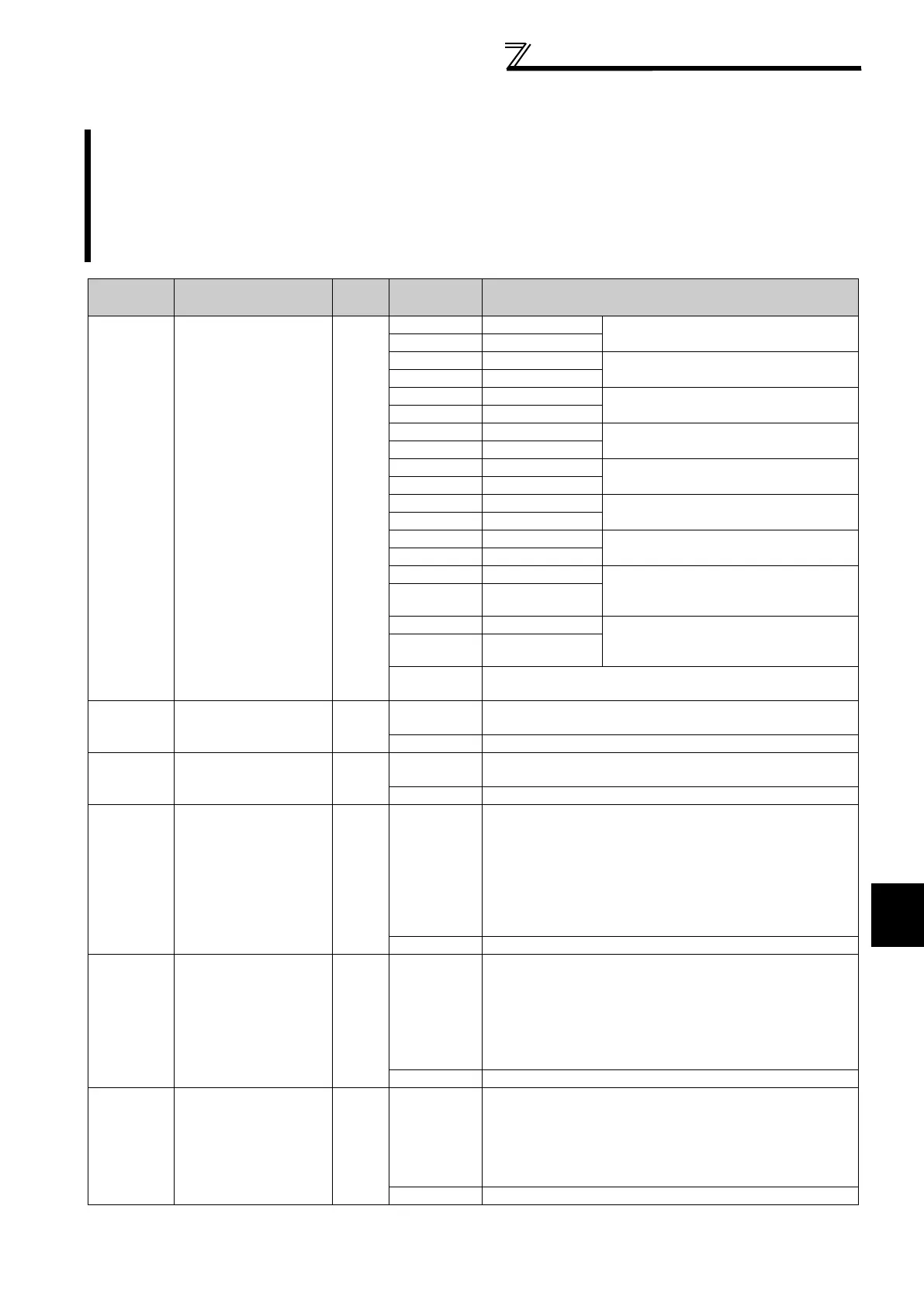
4.20.4 Second PID function (Pr.753 to Pr. 758, Pr.765 to Pr.769)
When the RT signal is ON and Pr. 753 Second PID action selection 9999, PID control is commanded by the
second function parameters.
When Pr. 753 = 9999, normal PID control is performed even if the second functions are valid.
When the control method is switched from the second PID control to the normal PID control, the integral value is
estimated. The integral value is estimated by calculating the integral term with the output frequency and the P
term. This method is same as when the control method changes to PID control when the frequency reaches the
automatic switchover frequency.
Parameter
Number
Name
Initial
Value
Setting
Range
Description
753
Second PID action
selection
9999
10
*2, 110 PID reverse action
Deviation value signal input
(terminal 1
*4)
11
*2, 111 PID forward action
20
*2, 120 PID reverse action
Measured value (terminal 4
*5)
Set point (terminal 2
*4 or Pr. 133)
21
*2, 121 PID forward action
40
*2, 140 PID reverse action
Measured value (terminal 4
*5)
Set point input (L
ON
W
ORKS
, CC-Link, BACnet)
41 *2, 141 PID forward action
50
*2 PID reverse action
Deviation value signal input
(L
ON
W
ORKS
, CC-Link, BACnet)
51 *2 PID forward action
60
*2 PID reverse action
Measured value, set point input
(L
ON
W
ORKS
, CC-Link, BACnet)
61 *2 PID forward action
70
*6 PID reverse action
Deviation value signal input
(PLC function)
71
*6 PID forward action
80
*6 PID reverse action
Measured value, set point input
(PLC function)
81
*6 PID forward action
90
*6 PID reverse action Deviation value signal input
(PLC function)
(Not reflected to the inverter frequency)
91
*6 PID forward action
100
*6 PID reverse action Measured value, set point input
(PLC function)
(Not reflected to the inverter frequency)
101
*6 PID forward action
9999
Normal PID control is performed regardless of the second PID
control parameter settings.
754
Second PID control
automatic switchover
frequency
9999
0 to 400Hz
Set the frequency at which the control is automatically
changed to PID control while the RT signals is ON.
9999 Without second PID control automatic switchover function
755
*1
Second PID action set
point
9999
0 to 100%
*3
Set the set point for PID control, which is performed while the
RT signal is ON.
9999 Terminal 2 input is the set point while the RT signal is ON.
756
*1
Second PID
proportional band
100%
0.1 to 1000%
Set the proportional band for PID control, which is performed
while the RT signal is ON.
If the proportional band is narrow (parameter setting is small),
the manipulated variable varies greatly with a slight change of
the measured value. Hence, as the proportional band narrows,
the response sensitivity (gain) improves but the stability
deteriorates, e.g. hunting occurs.
Gain Kp = 1/proportional band
9999 Without second proportional band
757
*1
Second PID integral
time
1s
0.1 to 3600s
Set the PID integral time for PID control, which is performed
while the RT signal is ON.
When deviation step is input, time (Ti) is the time required for
integral (I) action to provide the same manipulated variable as
proportional (P) action.
As the integral time decreases, the set point is reached earlier
but hunting occurs more easily.
9999 Without second integral control
758
*1
Second PID differential
time
9999
0.01 to
10.00s
Set the PID differential time for PID control, which is performed
while the RT signal is ON.
When deviation lamp is input, time (Td) is the time required to
provide the manipulated variable of only the proportional (P)
action. As the differential time increases, greater response is
made to a deviation change.
9999 Without second differential control

 Loading...


