214
Communication operation and setting
4.19.6 Mitsubishi inverter protocol (computer link communication)
(1) Communication specifications
The communication specifications are given below.
(2) Communication procedure
*1 If a data error is detected and a retry must be made, execute retry operation with the user program. The inverter comes to trip if the number of
consecutive retries exceeds the parameter setting.
*2 On receipt of a data error occurrence, the inverter returns "reply data 3)" to the computer again. The inverter comes to trip if the number of
consecutive data errors reaches or exceeds the parameter setting.
You can perform parameter setting, monitor, etc. from the PU connector or RS-485 terminals of the inverter
using the Mitsubishi inverter protocol (computer link communication).
Item Description
Related
Parameters
Communication protocol Mitsubishi protocol (computer link) Pr. 551
Conforming standard EIA-485 (RS-485)
Number of inverters connected 1:N (maximum 32 units), setting is 0 to 31 stations
Pr. 117
Pr. 331
Communication
speed
PU connector Selected among 4800/9600/19200/38400bps Pr. 118
RS-485 terminal
Can be selected from 300, 600, 1200, 2400, 4800, 9600, 19200 and
38400bps
Pr. 332
Control protocol Asynchronous system
Communication method Half-duplex system
Communication
specifications
Character system ASCII (7 bits or 8 bits can be selected)
Pr. 119
Pr. 333
Start bit 1bit
Stop bit length 1 bit or 2 bits can be selected
Pr. 119
Pr. 333
Parity check Check (with even or odd parity) or no check can be selected
Pr. 120
Pr. 334
Error check Sum code check
Terminator CR/LF (presence or absence can be selected)
Pr. 124
Pr. 341
Waiting time setting Selectable between presence and absence
Pr. 123
Pr. 337
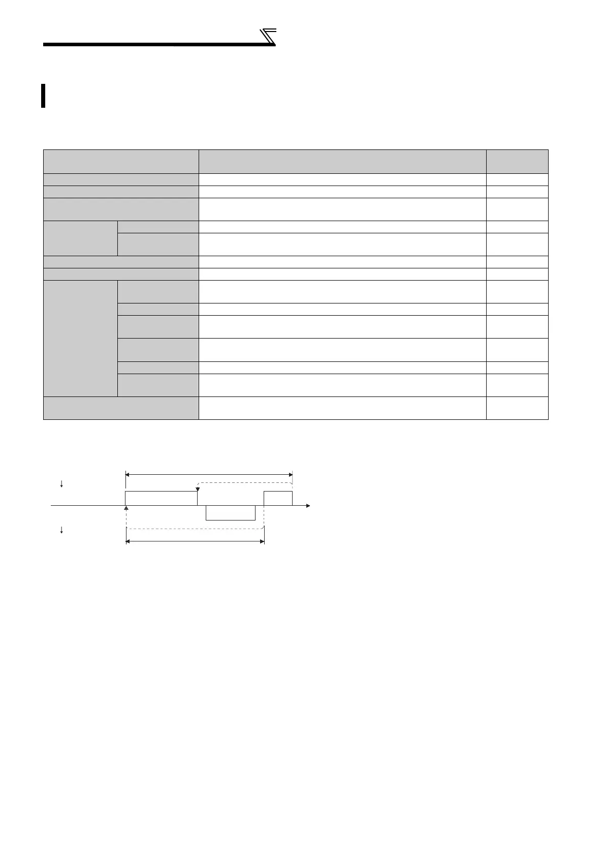
Data communication between the computer and
inverter is made in the following procedure.
1)Request data is sent from the computer to the
inverter. (The inverter will not send data unless
requested.)
2)After waiting for the waiting time
3)The inverter sends reply data to the computer in
response to the computer request.
4)After having waited for the time taken for inverter
processing
5)Answer from computer in response to reply data
3) is sent. (Even if 5) is not sent, subsequent
communication is made property.)
When data is read
When data is written
1) 5)4)
3)2)
*1
*2
Computer
(Data flow)
Inverter
Computer
(Data flow)
Inverter
Time

 Loading...


