255
Communication operation and setting
4.19.9 Operation by PLC function
(Pr. 414, Pr. 415, Pr. 498, Pr. 506 to Pr. 515, Pr. 826 to Pr. 865)
Refer to the FR-F700 PLC function programming manual for details of the PLC function.
I/O data read, write, etc. can be performed by accessing the inverter in the predetermined method using special
relays, special registers, etc.
Operation, parameter read/write, etc. can be performed in accordance with the created sequence programs (built
in the inverter) using input data from the control input terminals.
With the output signals, output data can be output to outside the inverter from the control output terminals as not
only the inverter's status signals but also pilot lamp ON/OFF, interlock and other control signals set freely by the
user.
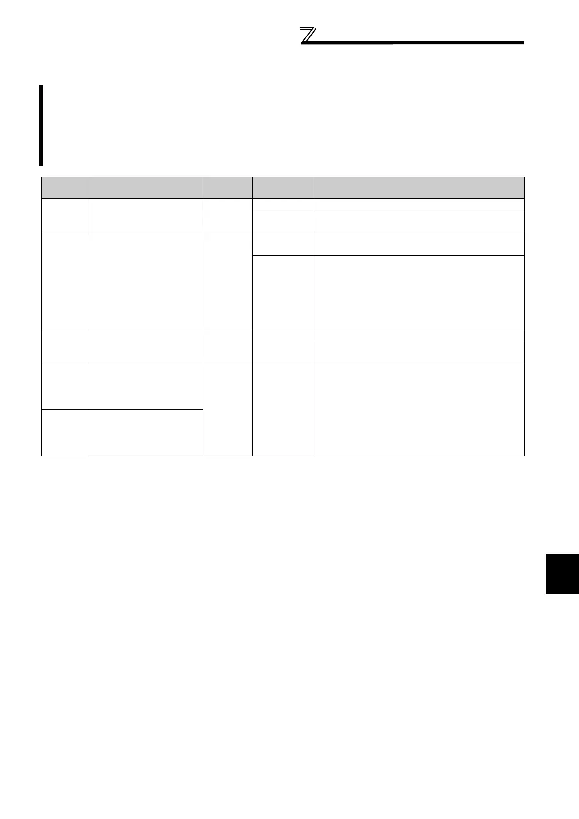
Parameter
Number
Name
Initial
Value
Setting
Range
Description
414
PLC function operation
selection
0
0 PLC function is invalid
1
PLC function is valid
(Inverter reset is necessary to make this setting valid.)
415
Inverter operation lock
mode setting
0
0
The inverter start signal is valid regardless of the
sequence program execution key.
1
The inverter start signal is valid only when the sequence
program execution key is set to RUN.
When the sequence program execution key is in the
STOP position, the inverter does not start if the inverter
start signal STF or STR is turned ON. (If the key is
switched from RUN to STOP during inverter operation,
the inverter is decelerated to a stop.)
498
PLC function flash memory
clear
0 0 to 9999
9696: Flash memory clear
Other than 9696:
Flash memory is not cleared
506 to 515 Parameter 1 to 10 for user
0 0 to 65535
Inverter parameters Pr. 506 to Pr. 515, Pr. 826 to Pr. 865
are used as user parameters.
Since this parameter area and the devices used with the
PLC function, D110 to D159, are accessible to each
other, the values set in Pr. 506 to Pr. 515, Pr. 826 to Pr. 865
can be used in a sequence program.
The result of operation performed in the sequence
program can also be monitored using Pr. 506 to Pr. 515,
Pr. 826 to Pr. 865.
826 to 865 Parameter 11 to 50 for user

 Loading...


