329
List of fault or alarm display
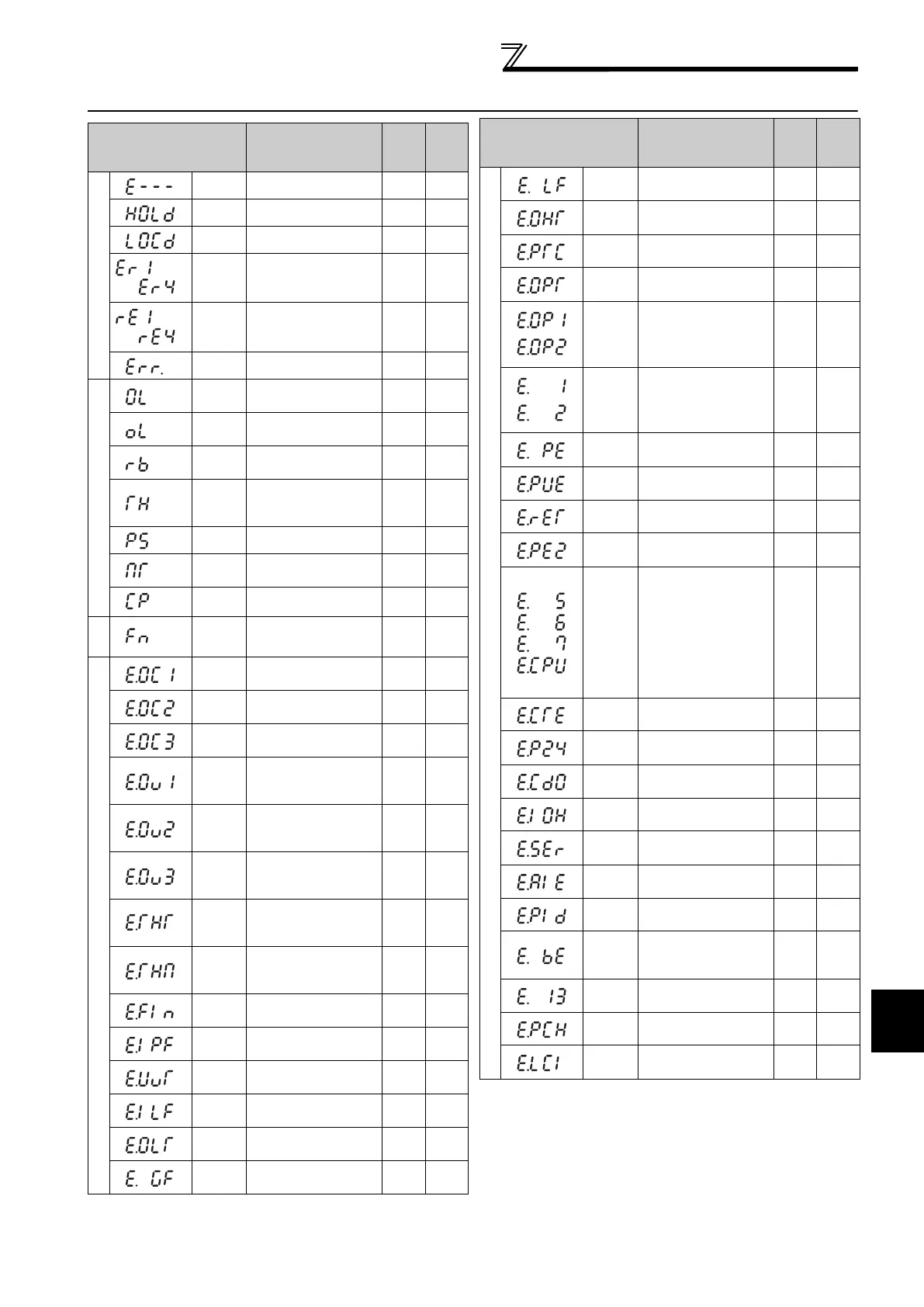
5.2 List of fault or alarm display
* If an error occurs when using the FR-PU04, "Fault 14" is displayed on
the FR-PU04.
Operation Panel
Indication
Name
Fault
data
code
Refer
to
Error message
E--- Faults history - 324
HOLD Operation panel lock - 330
LOCD
Password locked - 330
Er1 to 4
Parameter write error - 330
rE1 to 4
Copy operation error - 331
Err. Error - 331
Warnings
OL
Stall prevention
(overcurrent)
- 332
oL
Stall prevention
(overvoltage)
- 332
RB
Regenerative brake
pre-alarm
- 333
TH
Electronic thermal
relay function pre-
alarm
- 333
PS PU stop - 332
MT
Maintenance signal
output
- 333
CP Parameter copy - 333
Alarm
FN Fan alarm - 333
Fault
E.OC1
Overcurrent trip during
acceleration
16
(H10)
334
E.OC2
Overcurrent trip during
constant speed
17
(H11)
334
E.OC3
Overcurrent trip during
deceleration or stop
18
(H12)
334
E.OV1
Regenerative
overvoltage trip during
acceleration
32
(H20)
335
E.OV2
Regenerative
overvoltage trip during
constant speed
33
(H21)
335
E.OV3
Regenerative
overvoltage trip during
deceleration or stop
34
(H22)
335
E.THT
Inverter overload trip
(electronic thermal
relay function)
48
(H30)
335
E.THM
Motor overload trip
(electronic thermal
relay function)
49
(H31)
336
E.FIN Heatsink overheat
64
(H40)
336
E.IPF
Instantaneous power
failure
80
(H50)
336
E.UVT Undervoltage
81
(H51)
337
E.ILF* Input phase loss
82
(H52)
337
E.OLT Stall prevention stop
96
(H60)
337
E.GF
Output side earth
(ground) fault overcurrent
128
(H80)
337
to
to
Fault
E.LF Output phase loss
129
(H81)
337
E.OHT
External thermal relay
operation
144
(H90)
337
E.PTC*
PTC thermistor
operation
145
(H91)
338
E.OPT Option fault
160
(HA0)
338
E.OP1
E.OP2
Communication option
fault
161
(HA1)
162
(HA2)
338
E. 1
E. 2
Option fault
241
(HF1)
242
(HF2)
338
E.PE
Parameter storage
device fault
176
(HB0)
339
E.PUE PU disconnection
177
(HB1)
339
E.RET Retry count excess
178
(HB2)
339
E.PE2*
Parameter storage
device fault
179
(HB3)
339
E. 5
E. 6
E. 7
E.CPU
CPU fault
245
(HF5)
246
(HF6)
247
(HF7)
192
(HC0)
339
E.CTE
RS-485 terminal power
supply short circuit
193
(HC1)
339
E.P24
24VDC power output
short circuit
194
(HC2)
340
E.CDO*
Output current detection
value exceeded
196
(HC4)
340
E.IOH*
Inrush current limit
circuit fault
197
(HC5)
340
E.SER*
Communication fault
(inverter)
198
(HC6)
340
E.AIE* Analog input fault
199
(HC7)
340
E.PID* PID signal fault
230
(HE6)
340
E.BE
Brake transistor alarm
detection/internal
circuit fault
112
(H70)
336
E.13 Internal circuit fault
253
(HFD)
341
E. PCH*
Pre-charge fault
229
(HE5)
341
E.LCI*
4mA input fault
228
(HE4)
341
Operation Panel
Indication
Name
Fault
data
code
Refer
to
 Loading...


