14
Main circuit terminal specifications
2.2 Main circuit terminal specifications
2.2.1 Specification of main circuit terminal
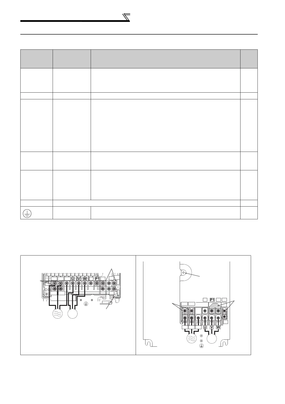
2.2.2 Terminal arrangement of the main circuit terminal, power supply and the motor
wiring
400V class
Terminal
Symbol
Terminal
Name
Description
Refer
to
page
R/L1,
S/L2,
T/L3
AC power
input
Connect to the commercial power supply.
Keep these terminals open when using the high power factor
converter (FR-HC, MT-HC) or power regeneration common converter
(FR-CV).
14
U, V, W Inverter output Connect a three-phase squirrel-cage motor.
14
R1/L11,
S1/L21
Power supply
for control
circuit
Connected to the AC power supply terminals R/L1 and S/L2. To
retain the fault display and fault output or when using the high power
factor converter (FR-HC, MT-HC) or power regeneration common
converter (FR-CV), remove the jumpers from terminals R/L1 and R1/
L11, and S/L2 and S1/L21 and apply external power to these
terminals.
The power capacity necessary when separate power is supplied from
R1/L11 and S1/L21 differs according to the inverter capacity.
00380 or less : 60VA, 00470 or more : 80VA
20
P/+, N/-
Brake unit
connection
Connect the brake unit (FR-BU2, FR-BU, BU and MT-BU5), power
regeneration common converter (FR-CV), high power factor converter
(FR-HC and MT-HC) or power regeneration converter (MT-RC).
31
P/+, P1
DC reactor
connection
For the 01160 or less, remove the jumper across terminals P/+ and
P1 and connect the DC reactor. (Be sure to connect the DC reactor
supplied with the 01800 or more.)
When a DC reactor is not connected, the jumper across terminals P/
+ and P1 should not be removed.
38
PR, PX Please do not remove or use terminals PR and PX or the jumper connected.
-
Earth (ground)
For earthing (grounding) the inverter chassis. Must be earthed
(grounded).
18
FR-F740-00023 to 00126-EC FR-F740-00170, 00250-EC
R/L1 S/L2 T/L3
N/-
P/+
PR
PX
R1/L11 S1/L21
IM
Charge lamp
Jumper
Jumper
Motor
Power
supply
R/L1 S/L2 T/L3
N/-
P/+
PR
PX
R1/L11 S1/L21
IM
Jumper
Jumper
Charge lamp
Motor
Power supply

 Loading...


