71
Adjustment of the output torque (current) of the motor
4.3 Adjustment of the output torque (current) of the motor
4.3.1 Manual torque boost (Pr. 0, Pr. 46)
(2) Set multiple torque boost (RT signal, Pr. 46)
Use the second torque boost when changing the torque boost according to application or when using multiple
motors by switching between them by one inverter.
Pr. 46 Second torque boost is valid when the RT signal turns ON.
Purpose Parameter that must be Set Refer to Page
Set starting torque manually Manual torque boost Pr. 0, Pr. 46 71
Automatically control output current
according to load
Simple magnetic flux
vector control
Pr. 71, Pr. 80, Pr. 90 72
Compensate for motor slip to secure
low-speed torque
Slip compensation Pr. 245 to Pr. 247 73
Limit output current to prevent inverter
trip
Stall prevention operation
Pr. 22, Pr. 23, Pr. 66,
Pr. 154, Pr. 156, Pr. 157
74
Change the overload current rating
specifications
Multiple rating setting Pr. 570 79
You can compensate for a voltage drop in the low-frequency range to improve motor torque reduction in the low-
speed range.
Motor torque in the low-frequency range can be adjusted to the load to increase the starting motor torque.
The starting torque boost can be changed by switching terminals.
Parameter
Number
Name Initial Value
Setting
Range
Description
0 Torque boost
00023 6%
0 to 30% Set the output voltage at 0Hz as %.
00038
to
00083 4%
00126, 00170 3%
00250 to 00770 2%
00930, 01160 1.5%
01800 or more 1%
46
*1
Second torque
boost
9999
0 to 30%
Set the torque boost value when the
RT signal is ON.
9999 Without second torque boost
*1 They can be set when Pr. 160 User group read selection = "0". (Refer to page 185.)
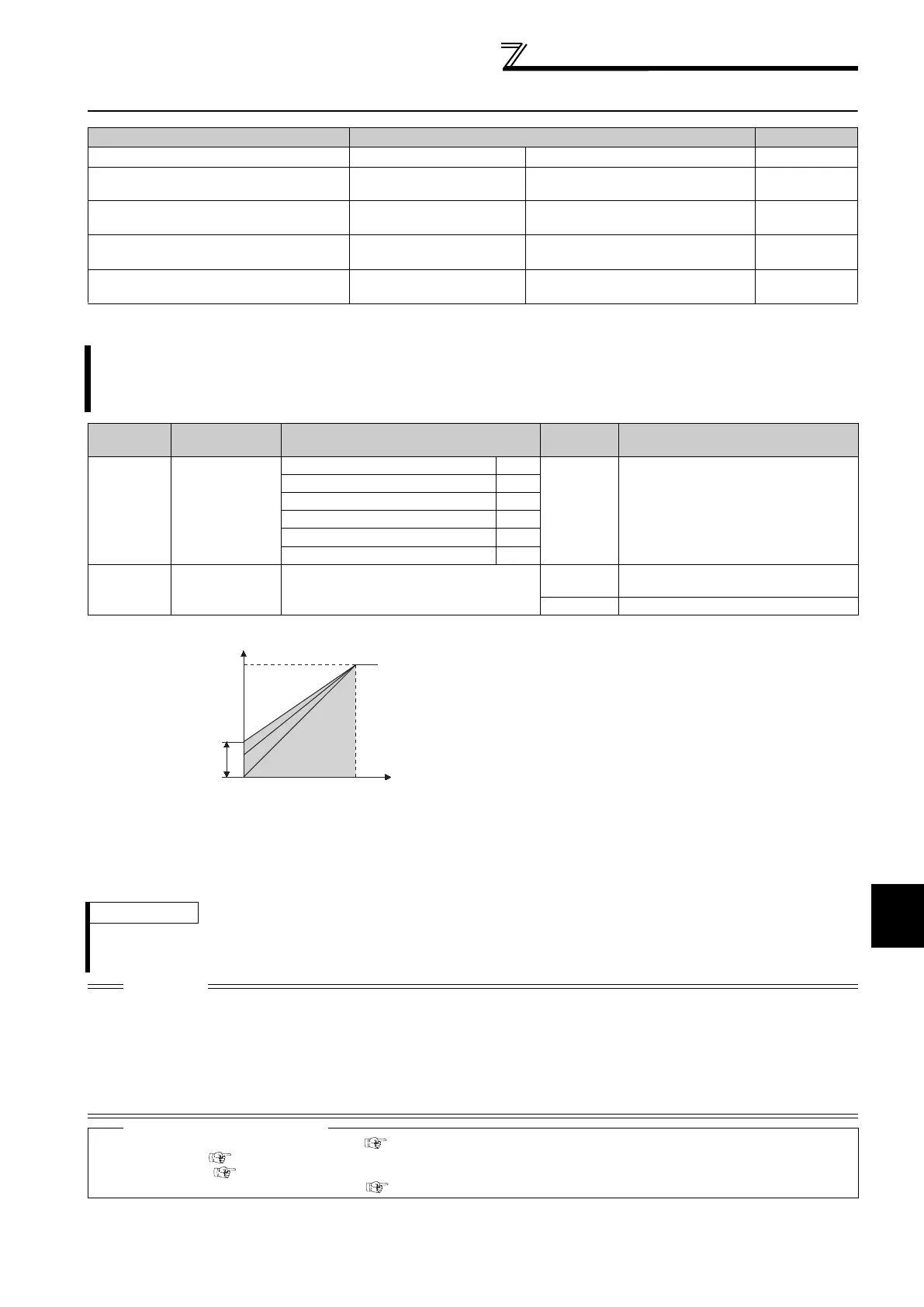
(1) Starting torque adjustment
On the assumption that Pr. 19 Base frequency voltage is
100%, set the output voltage at 0Hz in % in Pr. 0 (Pr. 46).
Adjust the parameter little by little (about 0.5%), and check
the motor status each time. If the setting is too large, the
motor will overheat. The guideline is about 10% at the
greatest.
REMARKS
The RT signal acts as the second function selection signal and makes the other second functions valid. (Refer to page 119)
The RT signal is assigned to the RT terminal in the default setting. By setting "3" to any of Pr. 178 to Pr. 189 (Input terminal function
selection), you can assign the RT signal to the other terminal.
CAUTION
Increase the setting when the distance between the inverter and motor is long or when motor torque is insufficient in the low-
speed range. If the setting is too large, an overcurrent trip may occur.
The Pr. 0 and Pr. 46 settings are valid only when V/F control is selected.
When using the inverter dedicated motor (constant-torque motor) with the 00126 or 00170, set the torque boost value to 2%. If
the initial set Pr. 71 value is changed to the setting for use with a constant-torque motor, the Pr. 0 setting changes to the
corresponding value in above.
Changing the terminal assignment using Pr. 178 to Pr. 189 (input terminal function selection) may affect the other functions. Please
set parameters after confirming the function of each terminal.
Parameters referred to
Pr. 3 Base frequency, Pr. 19 Base frequency voltage Refer to page 82
Pr. 71 Applied motor Refer to page 105
Pr. 80 Motor capacity Refer to page 72
Pr. 178 to Pr. 189 (Input terminal function selection) Refer to page 117
Output
voltage
r. 0
r.46
Setting
range
Base
frequency
0
100%
Output
frequency
(Hz)

 Loading...


