27
Control circuit specifications
2.3.3 Control circuit terminal layout
(1) Wiring method
(2) Common terminals of the control circuit (PC, 5, SE)
Terminals PC, 5, and SE are all common terminals (0V) for I/O signals and are isolated from each other. Do not
earth(ground) these terminals.
Avoid connecting the terminal PC and 5 and the terminal SE and 5.
Terminal PC is a common terminal for the contact input terminals (STF, STR, STOP, RH, RM, RL, JOG, RT, MRS, RES,
AU, CS).
The open collector circuit is isolated from the internal control circuit by photocoupler.
Terminal 5 is a common terminal for frequency setting signal (terminal 2, 1 or 4), analog current output terminal (CA)
and analog output terminal AM.
It should be protected from external noise using a shielded or twisted cable.
Terminal SE is a common terminal for the open collector output terminal (RUN, SU, OL, IPF, FU).
The contact input circuit is isolated from the internal control circuit by photocoupler.
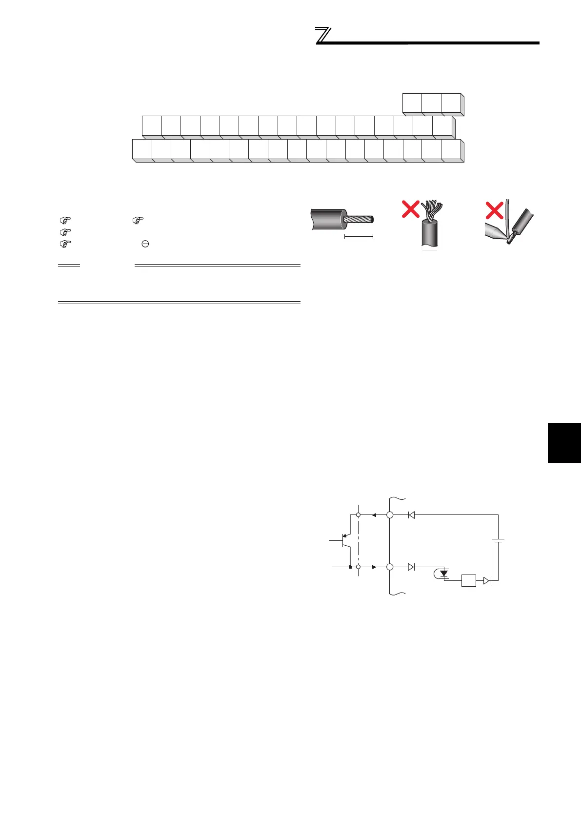
(3) Signal inputs by contactless switches
Loosen the terminal screw and insert the cable into the
terminal.
Screw Size: M3 Tightening Torque: 0.5N·m to 0.6N·m
Cable size: 0.3mm
2
to 0.75mm
2
Screwdriver:Small flathead screwdriver (Edge thickness:
0.4mm/Edge width: 2.5mm)
Wire the stripped cable after twisting it to prevent it from
becoming loose. In addition, do not solder it.
The contacted input terminals of the inverter (STF, STR, STOP,
RH, RM, RL, JOG, RT, MRS, RES, AU, CS) can be controlled
using a transistor instead of a contacted switch as shown on the
right.
External signal input using transistor
STOP
AURHRM
RL
C2B2A2C1B1A1
OLIPFSURUNSE14521010EAMPC
FU
MRS
JOG CS
RES STF STR PC
CA SD PC
RT
CAUTION
Undertightening can cause cable disconnection or malfunction.
Overtightening can cause a short circuit or malfunction due to
damage to the screw or unit.
6mm
PC
R
STF, etc.
+24V
Inverter
 Loading...


