26
Control circuit specifications
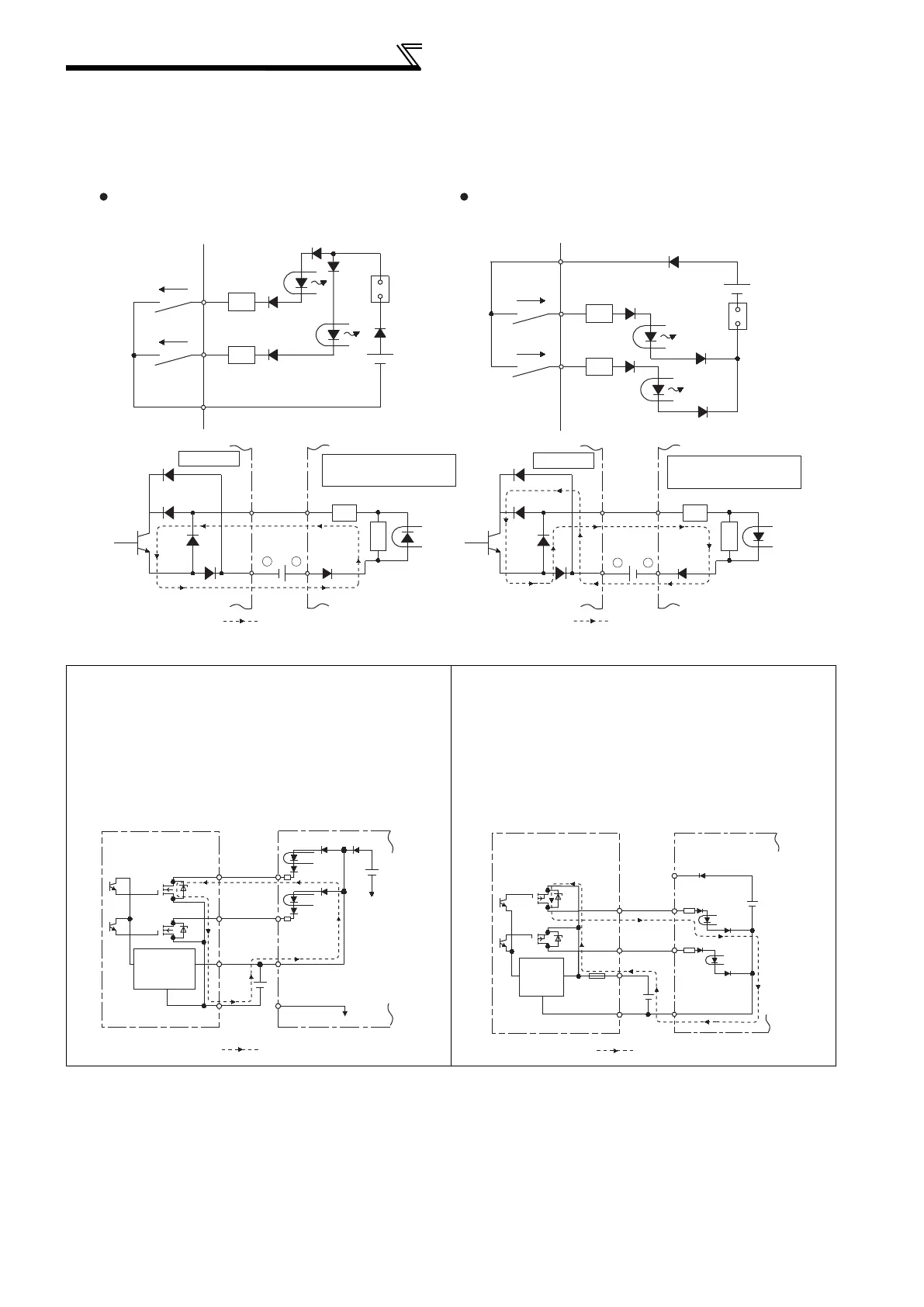
Sink logic and source logic
In sink logic, a signal switches ON when a current flows from the corresponding signal input terminal.
Terminal SD is common to the contact input signals. Terminal SE is common to the open collector output signals.
In source logic, a signal switches ON when a current flows into the corresponding signal input terminal.
Terminal PC is common to the contact input signals. Terminal SE is common to the open collector output signals.
When using an external power supply for transistor output
Sink logic type
Use terminal PC as a common terminal, and perform
wiring as shown below. (Do not connect terminal SD of
the inverter with terminal 0V of the external power
supply. When using terminals PC and SD as a 24VDC
power supply, do not install a power supply in parallel in
the outside of the inverter. Doing so may cause a
malfunction due to undesirable current.)
Source logic type
Use terminal SD as a common terminal, and perform
wiring as shown below. (Do not connect terminal PC of
the inverter with terminal +24V of the external power
supply. When using terminals PC and SD as a 24VDC
power supply, do not install an external power supply in
parallel with the inverter. Doing so may cause a
malfunction in the inverter due to undesirable currents.)
Current
PC
STF
R
STR
R
Source logic
Source
connecto
Current
SD
STF
R
STR
R
Sink
connector
Sink logic
Current flow concerning the input/output signal
when sink logic is selected
Current flow concerning the input/output signal
when source logic is selected
DC input (source type)
<Example: QX80>
24VDC
RUN
SE
TB1
TB18
R
Inverter
R
Current flow
+
-
+
-
DC input (sink type)
<Example: QX40>
Inverter
24VDC
RUN
SE
TB1
TB17
R
R
Current flow
TB1
TB2
TB17
TB18
24VDC
SD
PC
STR
STF
24VDC
(SD)
QY40P type transistor
output unit
Constant
voltage
circuit
Current flow
Inverter
PC
TB1
TB2
TB17
TB18
STF
STR
SD
24VDC
(SD)
24VDC
QY80 type transistor
output unit
Constant
voltage
circuit
Fuse
Current flow
Inverter
 Loading...


