33
Connection of stand-alone option units
2.4.2 Connection of the brake unit (FR-BU/MT-BU5)
When connecting the brake unit (FR-BU(H)/MT-BU5) to improve the brake capability at deceleration, make connection
as shown below.
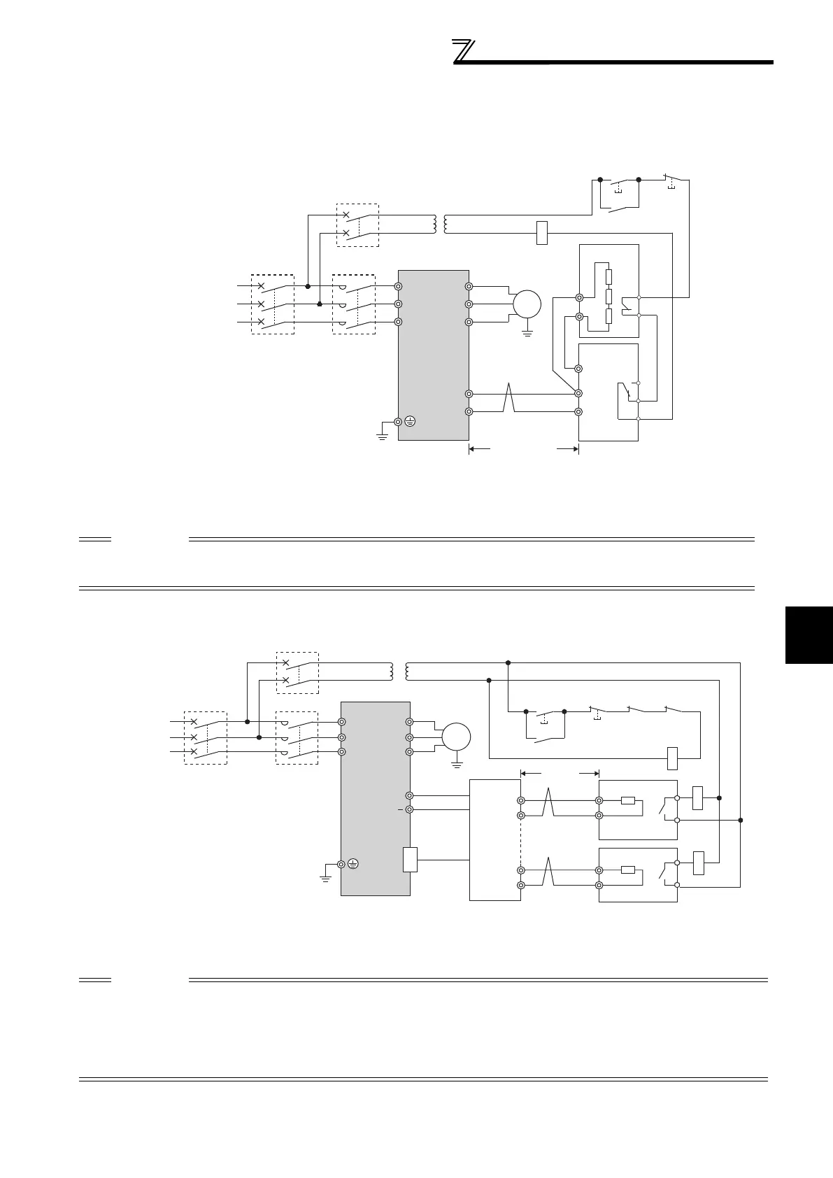
(1) Connection with the FR-BU (01160 or less)
(2) Connection with the MT-BU5 (01800 or more)
After making sure that the wiring is correct, set "1" in Pr.30 Regenerative function selection. (Refer to page 108)
*1 Connect the inverter terminals (P/+, N/-) and brake unit (FR-BU (H)) terminals so that their terminal signals match
with each other. (Incorrect connection will damage the inverter.)
*2 When the power supply is 400V class, install a step-down transformer.
*3 The wiring distance between the inverter, brake unit (FR-BU) and resistor unit (FR-BR) should be within 5m. If
twisted wires are used, the distance should be within 10m.
CAUTION
If the transistors in the brake unit should become faulty, the resistor can be unusually hot, causing a fire. Therefore, install a
magnetic contactor on the inverter’s input side to configure a circuit so that a current is shut off in case of fault.
Do not remove a jumper across terminal P/+ and P1 except when connecting a DC reactor.
*1 When the power supply is 400V class, install a step-down transformer.
*2 The wiring length between the resistor unit and brake resistor should be 10m maximum when wires are
twisted and 5m maximum when wires are not twisted.
CAUTION
Install the brake unit in a place where a cooling air reaches the brake unit heatsink and within a distance of the cable supplied
with the brake unit reaches the inverter.
For wiring of the brake unit and inverter, use an accessory cable supplied with the brake unit. Connect the main circuit cable to
the inverter terminals P/+ and N/- and connect the control circuit cable to the CN8 connector inside by making cuts in the
rubber bush at the top of the inverter for leading the cable.
The brake unit which uses multiple resistor units has terminals equal to the number of resistor units. Connect one resistor unit
to one pair of terminal (P, PR).
U
V
W
P/+
N/−
R/L1
S/L2
T/L3
Motor
IM
Inverter
PR
N/−
P/+
P
HA
HB
HC
FR-BU
FR-BR
TH2
TH1
PR
*1 *1
Three-phase AC
power supply
MCCB
MC
OFFON
MC
T *2
MC
*3
5m or less
MC
R/L1
Motor
IM
Inverter
Brake unit
MT-BU5
Resistor unit
MT-BR5
S/L2
T/L3
U
V
P/+
N/
P
PR
P
PR
P
PR
P
TH1
TH2
PR
CN8
W
Three-phase
AC power
supply
MCCB
TH1
TH2
MC
OFFON
MC
CR1 CR2
CR1
CR2
T
*1
5m or
less
*2
 Loading...


