34
Connection of stand-alone option units
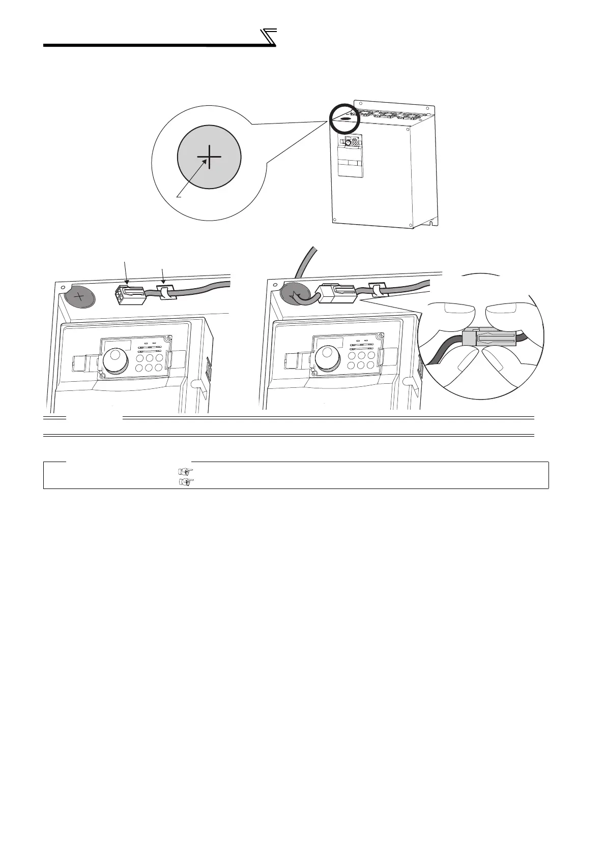
<Inserting the CN8 connector>
Make cuts in rubber bush of the upper portion of the inverter and lead a cable.
1) Make cuts in the rubber bush for leading the CN8 connector cable with a nipper or cutter knife.
2) Insert a connector on the MT-BU5 side through a rubber bush to connect to a connector on the inverter side.
CAUTION
Clamp the CN8 connector cable on the inverter side with a wire clamp securely.
Parameters referred to
Pr. 30 Regenerative function selection Refer to page 108
Pr. 70 Special regenerative brake duty Refer to page 108
Rubber bushes
Make cuts in
rubber bush
Insert the connector until
you hear a click sound.
 Loading...


