19
Main circuit terminal specifications
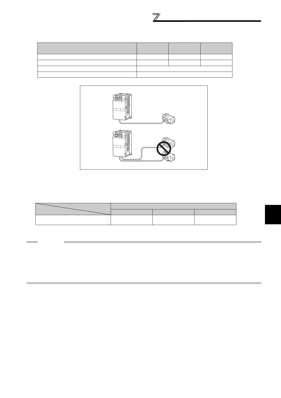
(3) Total wiring length
The overall wiring length for connection of a single motor or multiple motors should be within the value in the table below.
* For the 01800 or more, the setting range of Pr. 72 PWM frequency selection is "0 to 6".
When driving a 400V class motor by the inverter, surge voltages attributable to the wiring constants may occur at the
motor terminals, deteriorating the insulation of the motor.
Take the following measures 1) or 2) in this case. (Refer to page 46)
1) Use a "400V class inverter-driven insulation-enhanced motor" and set frequency in Pr. 72 PWM frequency selection
according to wiring length
2) Connect the surge voltage suppression filter (FR-ASF-H/FR-BMF-H) to the or less andthe sine wave filter (MT-
BSL/BSC) to the or more on the inverter outputside.
(4) Cable size of the control circuit power supply (terminal R1/L11, S1/L21)
· Terminal Screw Size: M4
· Cable size: 0.75mm
2
to 2mm
2
· Tightening torque: 1.5N·m
Pr. 72 PWM frequency selection Setting
(carrier frequency) *
00023 00038
00052 or
More
2 (2kH) or less 300m 500m 500m
3 (3kHz), 4 (4kHz) 200m 300m 500m
5 (5kHz) to 9 (9kHz) 100m
10 (10kHz) or more 50m
Total wiring length (00052 or more)
Wiring Length
50m or less 50m to 100m exceeding 100m
Pr. 72 PWM frequency selection Setting
(carrier frequency)
14.5kHz or less 9kHz or less 4kHz or less
CAUTION
· Especially for long-distance wiring, the inverter may be affected by a charging current caused by the stray capacitances of the
wiring, leading to a malfunction of the overcurrent protective function or fast response current limit function or a malfunction or fault
of the equipment connected on the inverter output side. If fast-response current limit function malfunctions, disable this function.
(For Pr.156 Stall prevention operation selection, refer to page 74.)
· For details of Pr. 72 PWM frequency selection , refer to page 164. (When using an optional sine wave filter (MT-BSL/BSC) for the
01800 or more, set "25" in Pr.72 (2.5kHz)).
· For explanation of surge voltage suppression filter (FR-ASF-H/FR-BMF-H) and sine wave filter (MT-BSL/BSC), refer to the
manual of each option.
500m or less
300m
300m
300m + 300m = 600m
 Loading...


