176
Frequency setting by analog input (terminal 1, 2, 4)
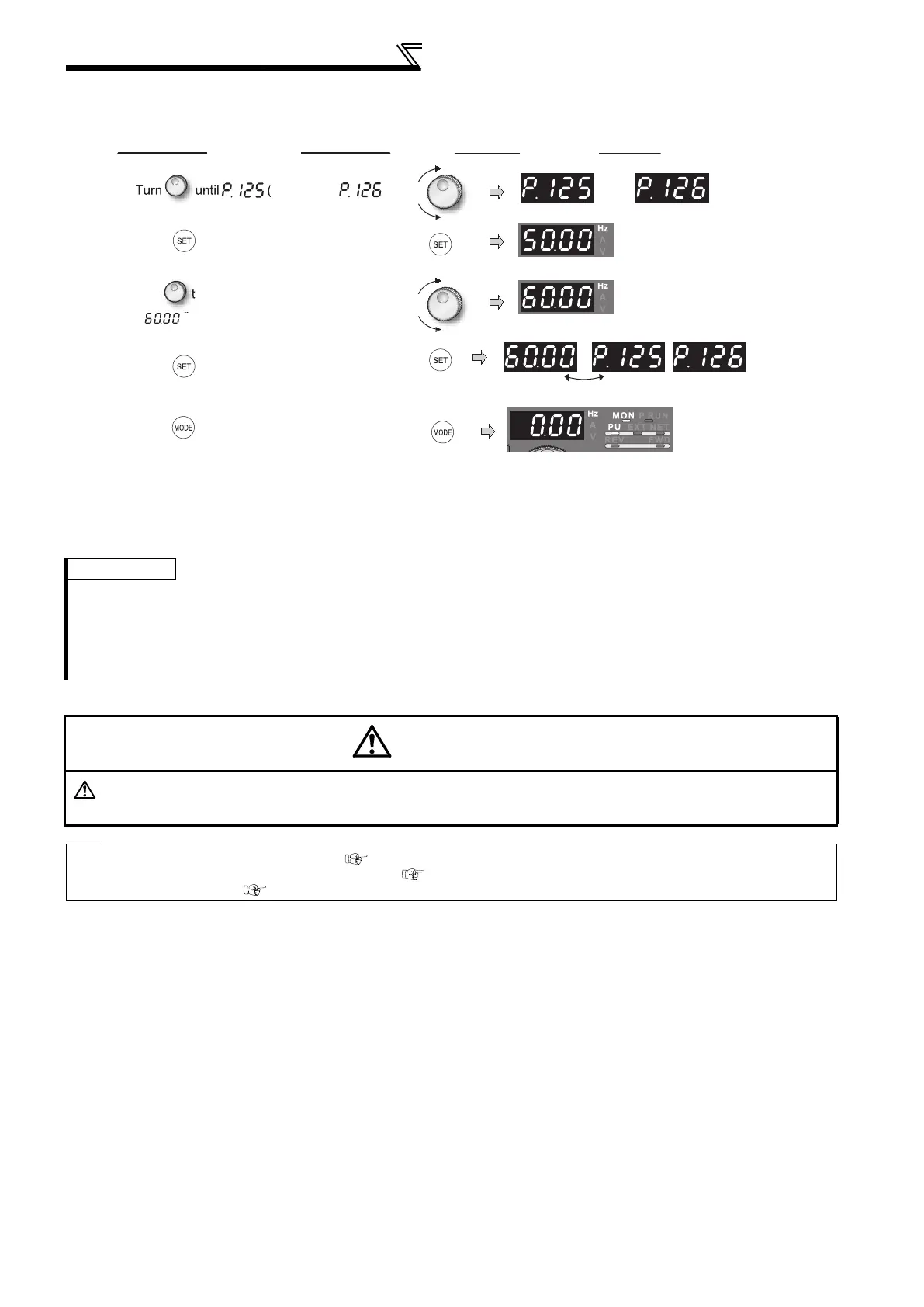
(c) Method to adjust only the frequency without adjustment of a gain voltage (current).
(When changing the gain frequency from 50Hz to 60Hz)
REMARKS
Changing C4 (Pr. 903) or C7 (Pr. 905) (gain adjustment) value will not change the Pr. 20 value. The input of terminal 1 (frequency
setting auxiliary input) is added to the speed setting signal.
For the operating procedure using the parameter unit (FR-PU04/FR-PU07), refer to the FR-PU04/FR-PU07 instruction manual.
When setting the value to 120Hz or more, it is necessary to set Pr. 18 High speed maximum frequency to 120Hz or more. (Refer to
page 80)
Make the bias frequency setting using calibration parameter C2 (Pr. 902) or C5 (Pr. 904). (Refer to page 173)
CAUTION
Be cautious when setting any value other than "0" as the bias frequency at 0V (0mA). Even if a speed command
is not given, merely turning ON the start signal will start the motor at the preset frequency.
Parameters referred to
Pr. 20 Acceleration/deceleration reference frequency Refer to page 94
Pr. 73 Analog input selection, Pr. 267 Terminal 4 input selection Refer to page 166
Pr. 79 Operation mode selection Refer to page 190
Display
Operation
Flicker...Parameter setting complete!!
1.
Pr. 125) or
(Pr. 126
appears.
4.
Press to set.
5.
Mode/monitor check
Press twice to choose the
monitor/frequency monitor.
or
Terminal 2 input Terminal 4 input
Terminal 2 input Terminal 4 input
3.
r
o c
an
e t
e set va
ue to
2.
Press to show the currently set value.
(50.00Hz)
6.
Apply a voltage across the inverter
terminals 2-5 (across 4-5) and turn on the
start command (STF, STR).
Operation starts at 60Hz.

 Loading...


