332
Causes and corrective actions
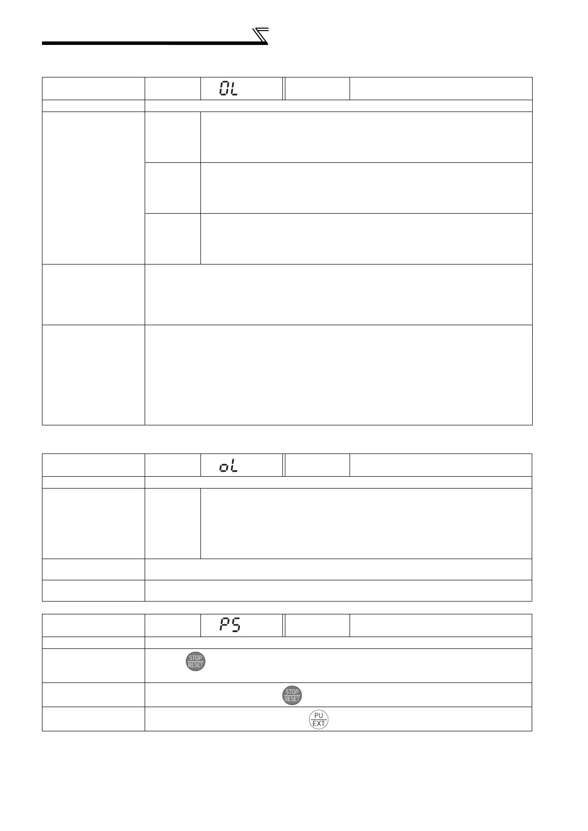
(2) Warnings
When the protective function is activated, the output is not shut off.
Operation Panel
Indication
OL
FR-PU04
FR-PU07(-01)
OL
Name
Stall prevention (overcurrent)
Description
During
acceleration
When the output current of the inverter exceeds the stall prevention operation level (Pr.
22 Stall prevention operation level, etc.), this function stops the increase in frequency until
the overload current decreases to prevent the inverter from resulting in overcurrent trip.
When the overload current has decreased below stall prevention operation level, this
function increases the frequency again.
During
constant
speed
operation
When the output current of the inverter exceeds the stall prevention operation level (Pr.
22 Stall prevention operation level, etc.), this function lowers the frequency until the
overload current decreases to prevent overcurrent trip. When the overload current has
decreased below stall prevention operation level, this function increases the frequency
up to the set value.
During
deceleration
When the output current of the inverter exceeds the stall prevention operation level (Pr.
22 Stall prevention operation level, etc.), this function stops the decrease in frequency until
the overload current decreases to prevent the inverter from resulting in overcurrent trip.
When the overload current has decreased below stall prevention operation level, this
function decreases the frequency again.
Check point
Check that the Pr. 0 Torque boost setting is not too large. (V/F control)
Check that the Pr. 7 Acceleration time and Pr. 8 Deceleration time settings are not too small.
Check that the load is not too heavy.
Are there any failure in peripheral devices?
Check that the Pr. 13 Starting frequency is not too large.
Check that the Pr. 22 Stall prevention operation level is appropriate.
Corrective action
Increase or decrease the Pr. 0 Torque boost value by 1% and check the motor status. (V/F control)
(Refer to page 71.)
Set a larger value in Pr. 7 Acceleration time and Pr. 8 Deceleration time. (Refer to page 94.)
Reduce the load weight. Try Simple magnetic flux vector control (Pr. 80).
Check the peripheral devices.
Adjust the Pr.13 setting. Change the Pr. 14 Load pattern selection setting. (V/F control)
Set stall prevention operation current in Pr. 22 Stall prevention operation level. (The initial value is
110%
*1
.) The acceleration/deceleration time may change. Increase the stall prevention operation level with
Pr. 22 Stall prevention operation level, or disable stall prevention with Pr. 156 Stall prevention operation
selection. (Use Pr. 156 to set either operation continued or not at OL operation.)
*1 120% when LD is selected
Operation Panel
Indication
oL
FR-PU04
FR-PU07(-01)
oL
Name
Stall prevention (overcurrent)
Description
During
deceleration
If the regenerative energy of the motor becomes excessive and exceeds the
regenerative energy consumption capability, this function stops the decrease in
frequency to prevent overvoltage trip. As soon as the regenerative energy has
decreased, deceleration resumes.
If the regenerative energy of the motor becomes excessive when regeneration
avoidance function is selected (Pr. 882 = 1), this function increases the speed to
prevent overvoltage trip. (Refer to page 184.)
Check point
Check for sudden speed reduction.
Regeneration avoidance function (Pr. 882 to Pr. 886) is being used? (Refer to page 294.)
Corrective action
The deceleration time may change.
Increase the deceleration time using Pr. 8 Deceleration time.
Operation Panel
Indication
PS
FR-PU04
FR-PU07(-01)
PS
Name
PU stop
Description
Stop with of PU is set in Pr. 75 Reset selection/disconnected PU detection/PU stop selection. (For Pr. 75,
refer to page 181.)
Check point
Check for a stop made by pressing of the operation panel.
Corrective action
Turn the start signal OFF and release with .

 Loading...


