6
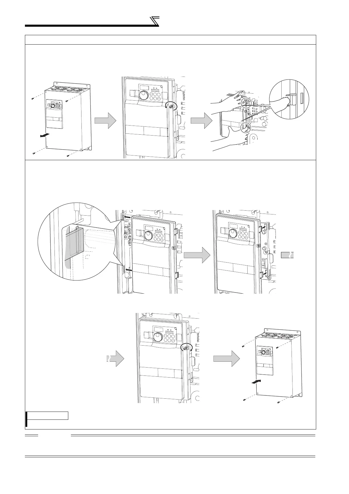
Method of removal and reinstallation of the
front cover
FR-F740-00770-EC or more
Removal
Reinstallation
CAUTION
1. Fully make sure that the front cover has been reinstalled securely. Always tighten the installation screws of the front cover.
2. The same serial number is printed on the capacity plate of the front cover and the rating plate of the inverter. Before reinstalling the
front cover, check the serial numbers to ensure that the cover removed is reinstalled to the inverter from where it was removed.
Front cover 2
Front cover 1
Installation hook
1) Remove installation screws on
the front cover 1 to remove the
front cover 1.
2) Loosen the installation
screws of the front cover 2.
3) Pull the front cover 2 toward you to
remove by pushing an installation
hook on the right side using left
fixed hooks as supports.
Front cover 2 Front cover 2
Front cover 2
Front cover 1
1) Insert the two fixed hooks on the left side of the
front cover 2 into the sockets of the inverter.
2) Using the fixed hooks as supports, securely
press the front cover 2 against the inverter.
(Although installation can be done with the
operation panel mounted, make sure that a
connector is securely fixed.)
3) Fix the front cover 2 with the
installation screws.
4) Fix the front cover 1 with the
installation screws.
REMARKS
For the FR-F740-04320 or more, the front cover 1 is separated into two parts.
 Loading...


