269
PID control
Take caution when the following condition is satisfied because the inverter recognizes the deviation value as a
negative (positive) value even though a positive (negative) deviation is given:
Pr. 934 PID display bias coefficient
> Pr. 935 PID display gain coefficient
To perform a reverse operation, set the forward operation in Pr. 128 PID action selection. To perform a forward
operation, set the reverse operation in Pr. 128. In this case, the PID output shutoff release level is (1000 - Pr. 577).
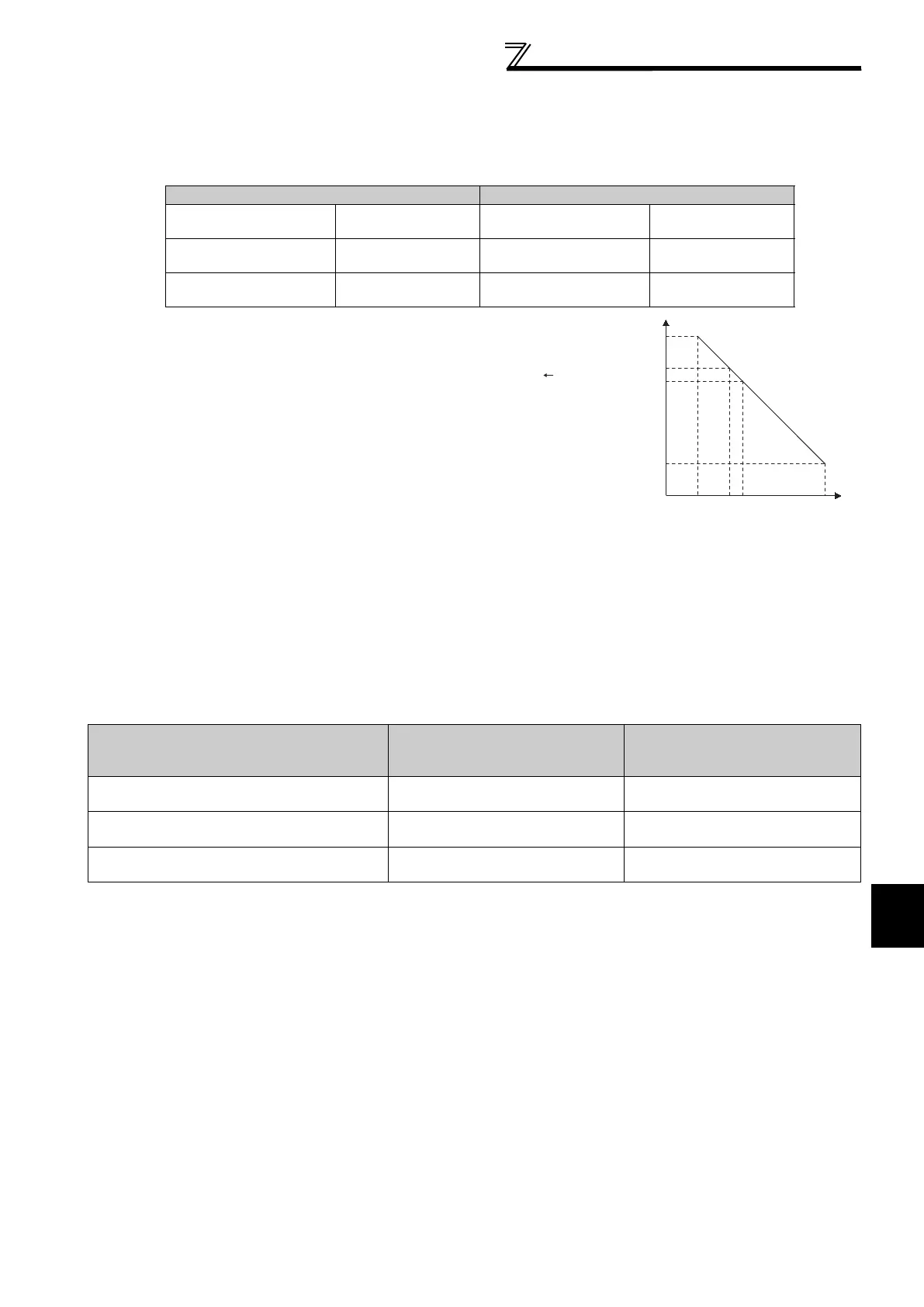
(Example) Set the following: Pr. 934 = "500" and
20% (4mA is applied), Pr. 935 = "100"
and 100% (20mA is applied).
When the set point=400 and the
measured value=360, the deviation is
+40 (>0), but the inverter recognizes the
deviation with -10% (<0). Because of
this, operation amount does not
increase in the reverse operation
setting.
The operation amount increases when
the forward operation is set.
To perform PID output shutoff release at
deviation of +40 or higher, set Pr. 577 =
"960."
(2) Analog input display unit changing (Pr. 241)
You can change the analog input display unit (%/V, mA) for analog input bias/gain calibration.
Depending on the terminal input specification set to Pr. 73, Pr. 267, and voltage/current input switch the display units
of C3(Pr. 902), C4(Pr. 903), C43(Pr. 934), C45(Pr. 935) change as shown below.
Pr. 934 < Pr. 935 (normal setting) Pr. 934 Pr. 935
Reverse operation
Reverse operation
setting to Pr. 128
Reverse operation
Forward operation
setting to Pr. 128
Forward operation
Forward operation
setting to Pr. 128
Forward operation
Reverse operation
setting to Pr. 128
PID output shutoff release
level
Pr. 577 - 1000
PID output shutoff release
level
1000 - Pr. 577
Analog Command (Terminal 4)
(according to Pr. 73, Pr. 267, and Voltage/Current
Input Switch)
Pr. 241 = 0 (Initial Value) Pr. 241 = 1
0 to 5V input
0 to 5V
displayed in 0 to 100%(0.1%).
0 to 100%
displayed in 0 to 5V(0.01V).
0 to 10V input
0 to 10V
displayed in 0 to 100%(0.1%).
0 to 100%
displayed in 0 to 10V(0.01V).
4 to 20mA input
0 to 20mA
displayed in 0 to 100%(0.1%).
0 to 100%
displayed in 0 to 20mA(0.01mA).
0
100%
500
20%
100
400
360
(0%) (25%)(35%) (100%)
Set point
Measured value
↓
Deviation -10%
*( ) indicates the deviation value
which the inverter can
recognize
Deviation +40

 Loading...


