293
PID control
REMARKS
When the second function signal (RT) is on, normal acceleration/deceleration time (Pr. 7, Pr. 8) is the same as second
acceleration/deceleration time (Pr. 44, Pr. 45).
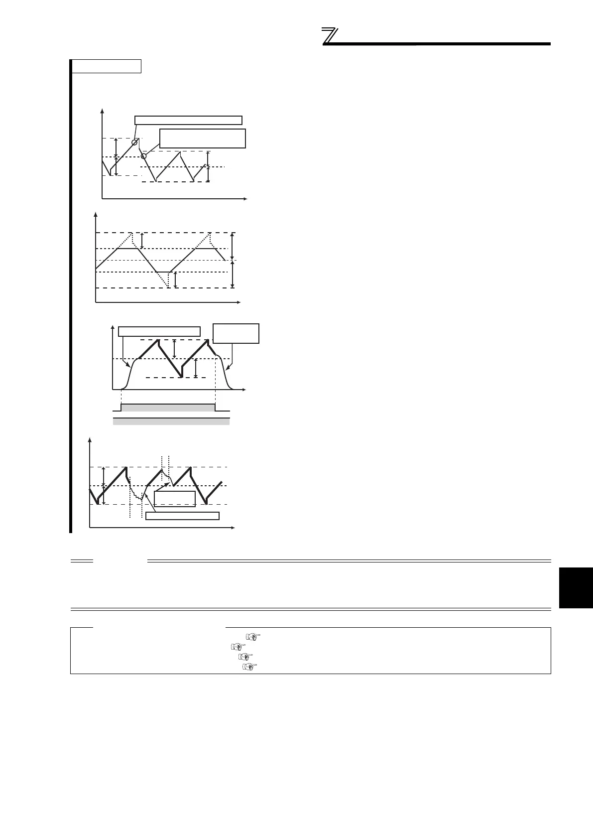
· If the set frequency (f0) and traverse operation parameters (Pr. 598 to
Pr. 597) are changed, pattern operation is performed at changed f0
after the output frequency reached f0 before change.
· When the output frequency exceeds Pr. 1 Maximum frequency or Pr.2
Minimum frequency, the output frequency is clamped at maximum/
minimum frequency while the set pattern exceeds the maximum/
minimum frequency.
· When the traverse function and S-pattern acceleration/deceleration
(Pr. 29 0) are selected, S-pattern acceleration/deceleration is
performed only in the areas where operation is performed in normal
Acceleration and deceleration time (Pr. 7, Pr. 8). For acceleration/
deceleration during traverse operation, linear acceleration/
deceleration is made.
· When stall prevention is activated during traverse operation, traverse
operation is stopped and normal operation is performed. When stall
prevention operation ends, the motor accelerates/decelerates to f0 in
normal acceleration/deceleration time (Pr. 7, Pr. 8). After the output
frequency reaches f0, traverse operation is again performed.
CAUTION
· When the value of amplitude inversion compensation amount (Pr. 594, Pr. 595) is too large, pattern operation as set is not
performed due to overvoltage shut-off and stall prevention.
· Changing the terminal assignment using Pr. 178 to Pr. 189 (input terminal function selection) may affect the other functions.
Please make setting after confirming the function of each terminal.
Parameters referred to
Pr. 1 Maximum frequency, Pr. 2 Minimum frequency Refer to page 80
Pr. 7 Acceleration time, Pr. 8 Deceleration time Refer to page 94
Pr. 29 Acceleration/deceleration pattern selection Refer to page 98
Pr.178 to Pr.189 (input terminal function selection) Refer to page 117
f0
Output frequency(Hz)
Time(s)
f1
f1
f0
f1
f1
Reflected on the action
at this point
F0 is rewritten at this point.
f0
Output frequency(Hz)
Time(s)
f1
f1
Pr.1
Pr.2
Clamped by Pr.1
Clamped by Pr.2
f0
Output frequency(Hz)
Time(s)
f1
f1
S-pattern acceleration
STF(STR)
signal
RH signal
ON
ON
S-pattern
deceleration
f0
Output frequency(Hz)
Time(s)
f1
f1
Accelerate as set in Pr. 7
Stall prevention operation
Stall prevention operation
Decelerate as
set in Pr. 8
 Loading...


