4.8 Using the DC Bias
4-34 ZM2371/ZM2372
To connect/disconnect the DUT, the output of external power should be set to
“0”. Once the DUT like inductor is disconnected while the bias current is
running, high voltage may be generated, thereby causing an damaging the LCR
meter.
If the temperature of DUT can be increased during measurement, do not touch it
until the temperature excessively drops after measurement. If high voltage or
current is applied on the DUT for a long time, high temperature may cause a
burn or DUT/ circumference can be burn out.
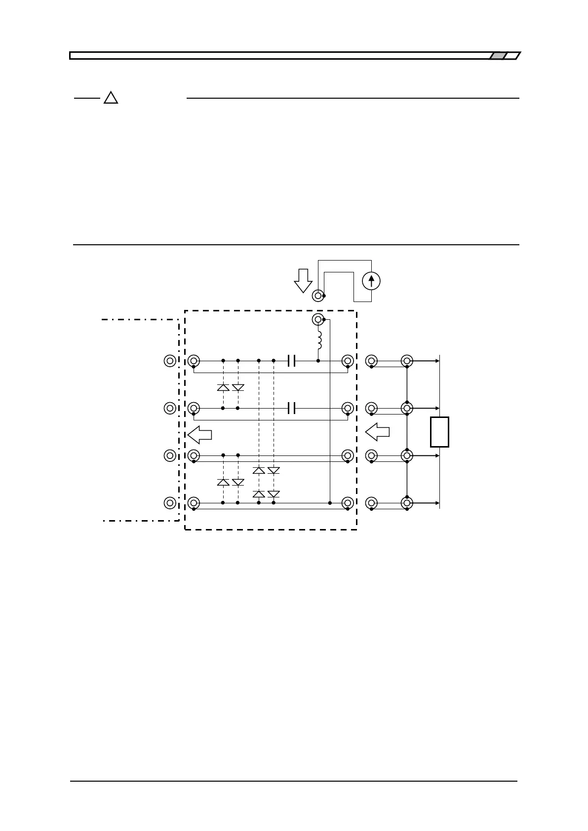
Element value: the following case shows the example of measurement taken at 1kHz
or more in frequency:
C1=20µF (Film capacitor)
C2=4.7µF (Film capacitor)
Increase the impedance of L1 excessively higher than that of DUT.
The external power should be isolated from the ground. If the insulation impedance is
low due to the high stray capacitance, LCR meter may get unstable, thus disabling
the measurement.
The rectifier diode, which has an excessive peak current capacitance for
preventing from damaging due to the bias current and also has a small
backward leak current, is suitable as the protective diode. When the
measurement signal level is 1Vrms, the number of series between H and L
should be approx 8 pieces.
Figure 4–8 External current bias circuit


 To Next Page