8.7 Performance Testing
8-5 ZM2371/ZM2372
8.7.3 Voltage Monitor Accuracy
Connection: H
CUR
and H
POT
terminals together → AC voltmeter input (– terminal)
L
CUR
and L
POT
terminals together → AC voltmeter input (+ terminal)
For the connection, use kelvin test lead or coaxial cable.
To use the coaxial cable, connect 4 shields all together.
The cable length should be approx 1m or less in total length.
Kelvin clip H terminal + terminal AC voltmeter
test lead, etc. L terminal – terminal
For the multimeter, which is activated by AC power, if large
capacitance to earth is connected to L terminal, LCR meter gets
unstable and correct measurement may not be done. Therefore, we
recommend you to connect +/– inversely. If it is possible to make
correct measurement, no need to connect inversely.
Setting: After initializing the setting, set the measurement frequency and
measurement signal level according to the contents in table stated below.
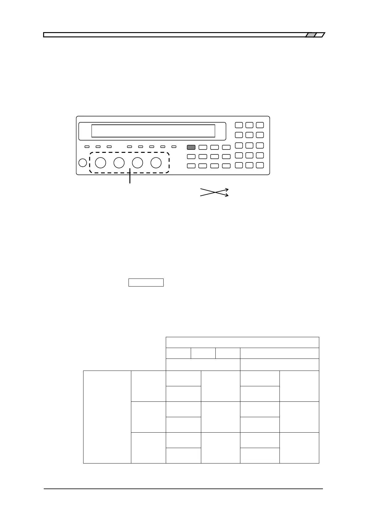
Press the
_
AUX DISP
_
key to display the auxiliary display selection menu,
and switch the auxiliary display into current monitor value and Voltage
monitor value.
Measurement: Measure the output voltage under each condition with the AC voltmeter.
Evaluation: If the values of voltage monitor are within the specification range in table
for the specified values of voltmeter, it is normal.
Spec. ± 4.0
Difference:
mVrms
Spec. ± 5.5
Difference:
mVrms
Spec. ± 22
Difference:
mVrms
Spec. ± 37
Difference:
mVrms
Spec. ± 102
Difference:
mVrms
Spec. ± 177
Difference:
mVrms