5.7 Status System
5-79 ZM2371/ZM2372
5.7.4 Operation Status
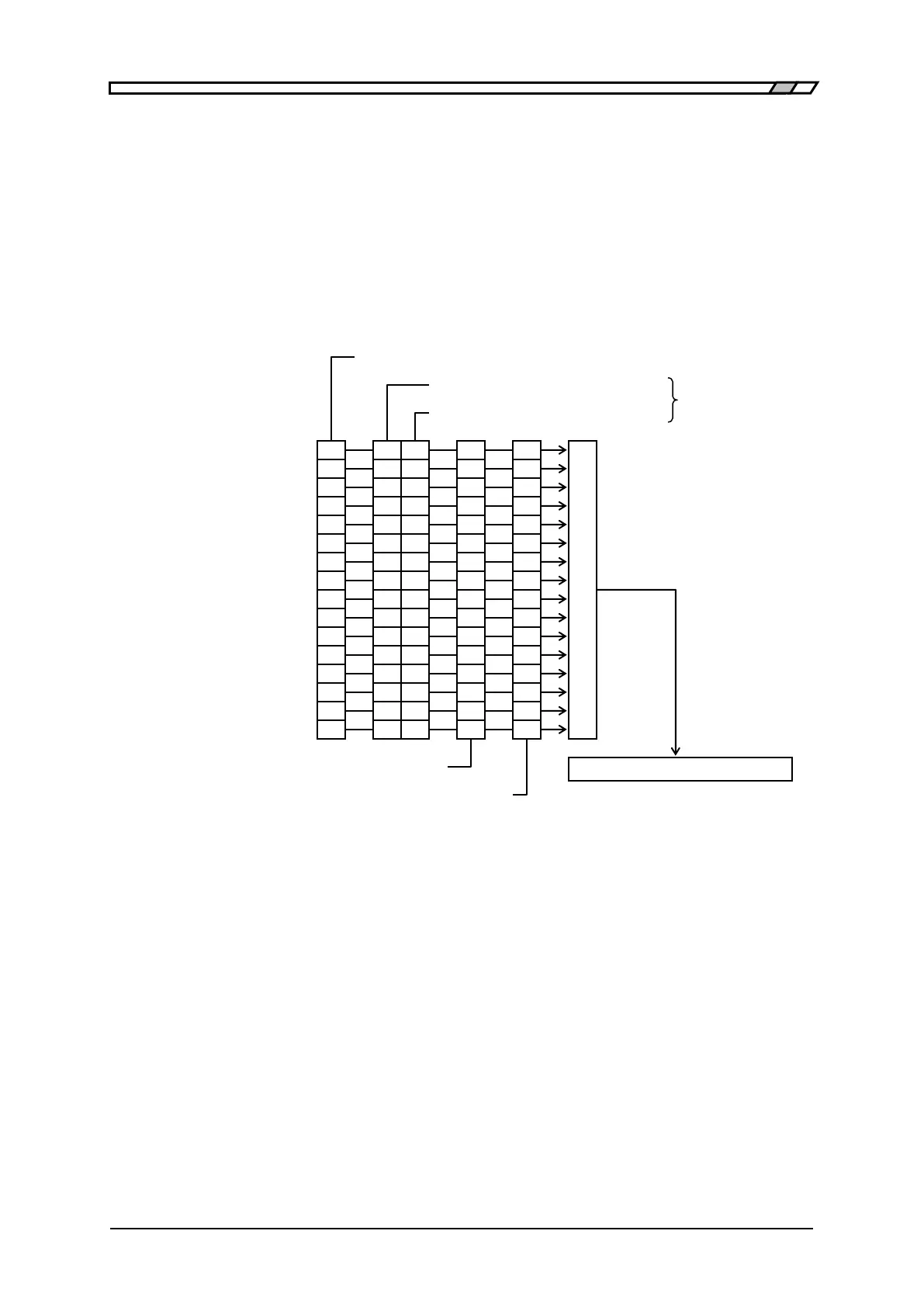
The operation status structure is shown on Figure 5-4.
As can be seen on Table 5-6, the operation condition register indicates ZM2371/ZM2372
status.
The transition filter detects a condition change and causes an event to occur. The filter
setting of ZM2371 / ZM2372 is fixed. The operation event register retains the events that
occurred. When the operation event enable register bits are set to 1, the corresponding
operation event register bits become valid. When at least one such bit is set to 1, the status
byte OPE bit is set to 1.
Figure 5–4 Operation status structure
OPTR (Positive transition filter)
ONTR (Negative transition filter)
(Operation event register) OPER
(Operation event enable register) OPEE
OPCR (Operation condition register)
Correction measuring CORR