NMC-WOLLARD 2021Truax Blvd., Eau Claire, WI 54703, Phone (715) 835-3151, Fax (715) 835-6625
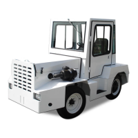
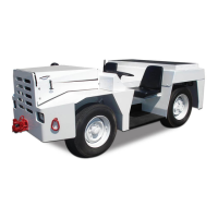
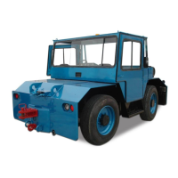
M100 Tow Tractor Manual No. 46052
PAGE 2
CHAPTER 1 GENERAL INFORMATION AND OPERATING INSTRUCTIONS
2 OPERATION
NOVEMBER 02, 2015
2.2.2 Instruments
1. The engine hour meter (if equipped) registers how many hours the
engine has operated. It is sealed and can record 99999.9 hours before it
returns to zero.
2. The fuel gauge shows the amount of fuel in the fuel tank. A sending unit
in the tank is connected to the gauge. The gauge is marked to indicate
the relative quantity of fuel in the tank. Keep the needle in the green part
of the gauge.
3. The oil pressure gauge (if equipped) indicates oil pressure only (not oil
level). It is marked 6 to 100 with intermediate index marks. If the gauge
registers in the red area, stop the engine and troubleshoot the problem.
4. The voltmeter (if equipped) registers voltage across the battery terminals.
The needle should be in the green area while the tractor is operating. If
the needle registers in the red while the tractor is operating, this indicates
that the battery is not being charged by the alternator. Stop the tractor and
inspect the battery, cables, and alternator connections.
5. The coolant temperature gauge (if equipped) shows the coolant
temperature in the engine’s water jacket. The gauge needle should rise
when the engine is started, then level out at between 150 and 200 as the
engine warms up. If the needle goes into the red, stop the engine and
check for a cooling system problem.
6. The transmission oil temperature gauge (if equipped) shows the
temperature of the transmission uid. Normal operating temperature is in
the 120F to 280F range. If the needle goes into the red, stop the engine
and troubleshoot the cause.
7. The Fuses for all electrical circuits (except the optional cab) are located
under the instrument panel in fuse blocks.
8. The CAN engine fault display shows engine fault codes for computer
controlled engines. See Chapter 5.
2.3 OPERATING THE ENGINE
2.3.1 Starting the Engine
Several things aect engine start, such as battery power, starter motor
performance, and oil viscosity.
1. Perform the daily service checks as detailed in Chapter 2.
2. Apply the parking brake.
3. Place the gear shift lever in N (neutral) position.
4. Gasoline or LPG only: Start engine.
5. Diesel: Hold rocker switch for about 15 seconds, until green indicator on
dash lights. Then turn ignition switch to START to crank engine.
6. Crank starter for no more than 15 seconds.