www.nordsonefd.com info@nordsonefd.com 800-556-3484 Sales and service of Nordson EFD dispensing systems are available worldwide.
EV Series Automated Dispensing Systems
5
Introduction
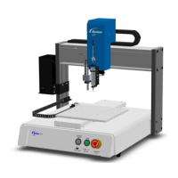
This manual provides installation, setup, programming, operation, and service information for all components of a
Nordson EFD EV Series automated dispensing system. Nordson EFD’s automated dispensing systems dispense
uid in a preprogrammed pattern onto a workpiece. They are specically designed and congured for use with
Nordson EFD industrial syringe barrel and valve systems. Automated dispensing systems offer the exibility of
working either as a stand-alone system or as a key part of an automated solution and are easily integrated into in-
line transfer systems, rotary tables, and pallet assembly lines.
The primary components of an automated dispensing system are the DispenseMotion
™
controller, the robot, and the
dispensing system components. The robot executes a computer program to dispense uid in a specic pattern onto
a workpiece. Programs are created using the DispenseMotion software installed on the DispenseMotion controller.
The dispensing system may be contact or non-contact, with material being dispensed through either a dispensing
tip or nozzle. For the purposes of this manual, “dispensing tip” refers to either a tip or a nozzle.
Using the precision-vision camera, the robot can automatically adjust the dispensing program for each workpiece,
allowing for variations in the workpiece position or orientation. To accomplish this, the software compares the
current workpiece location to within +/- 2.5 mm (0.098") of a reference location that is stored as an image le (called
a mark le) in the program. If the robot detects a difference in the X and Y positions and/or the angle of rotation of
the workpiece, it adjusts the dispensing path to correct for the difference.
Appendix A, Command Function Reference .................................................................................................................67
Appendix B, DXF File Import .........................................................................................................................................84
Overview of the DXF Screen ......................................................................................................................................84
Setting DXF Import Preferences ................................................................................................................................85
Importing a DXF File ..................................................................................................................................................86
Appendix C, QR Code Scanning Setup ........................................................................................................................89
Appendix D, Multi-Needle Setup and Use ....................................................................................................................92
Appendix E, Height Sensor Setup and Use ..................................................................................................................97
Appendix F, I/O Pin Function Setup ............................................................................................................................101
Contents (continued)