Do you have a question about the Nordson EFD E2V and is the answer not in the manual?
Warning about electrical hazards and safety procedures.
Specifies the maximum permissible air input pressure for the system.
Instruction to release pressure before servicing pressurized components.
Warning about hot surfaces and precautions to avoid burns.
Hazards associated with using halogenated hydrocarbon solvents with aluminum components.
Hazards of high pressure fluids and necessary precautions.
Defines responsibilities for ensuring equipment is operated by trained personnel.
Describes the proper and improper uses of the equipment.
Emphasizes compliance with ratings and approvals for the operating environment.
Provides essential safety instructions for personal protection during operation.
Instructions to prevent fire or explosion hazards during operation.
Recommended checks for maintaining equipment reliability and performance.
Safety guidelines for using and disposing of single-use components.
Steps to take when the system or equipment malfunctions.
Guidance on disposing of equipment and materials according to local codes.
Requirements for CE safety directives regarding system enclosures.
Guidelines for selecting a safe and suitable environment for robot installation.
Instructions for proper electrical connection and grounding of the system.
Safety precautions during robot operation and maintenance procedures.
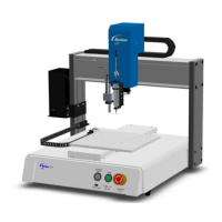
Identifies and illustrates the main components of the EV Series system.
Details the buttons and ports on the front panel of the EV system.
Details the ports and connectors on the back panel of the EV system.
Describes the features and functions of the system's camera.
Explains how to connect and use the optional joystick for robot control.
Instructions for safely unpacking the automated dispensing system components.
Steps for correctly positioning and connecting system components for installation.
Defines programs, commands, and their types used in the system.
Explains camera-to-tip and tip-to-workpiece offsets and their calibration.
Details how marks are used for workpiece recognition and orientation.
Describes the numeric keypad used for data entry in the software.
Procedure for viewing and changing system-level settings and parameters.
How to reset all system settings to their original factory defaults.
Procedure for setting or resetting a password to protect system settings.
Steps to confirm the correct robot model and tip detector selection.
Procedure for configuring the tip detector on EV systems.
Steps to adjust the camera focus and lighting for optimal image clarity.
Procedure for calibrating the camera's pixel-to-measurement conversion.
Explains how the system responds to Needle Z Detect and XY Adjust actions.
Details the IO Pin Function for user-configurable input/output conditions.
Configures how the system reacts when a mark cannot be found.
Procedure for updating system offsets after component changes.
Basic steps for creating, testing, and running dispensing programs.
Protects programs from unauthorized editing by locking them.
How to use the system to measure distances and diameters on a workpiece.
Example program for creating circular dispensing patterns.
How to utilize pre-programmed command sequences as starting points.
Incorporating marks for workpiece presence, correctness, and orientation checks.
Using Step & Repeat commands for patterns on multiple workpieces.
Using Block Start to enable/disable dispensing for individual workpieces in an array.
Step-by-step guide to powering on and executing a dispensing program.
Executing programs by scanning associated QR codes.
How to pause the system's operation during a dispense cycle.
Procedure for purging the dispensing system.
Steps for safely powering down the dispensing system components.
Lists standard cables for connecting dispensers and robots.
Describes available fixture plate sizes for mounting workpieces.
Facilitates remote input/output connections for functions like start/stop.
Optional component for automatic XY and Z height updates.
Detects workpiece height variations and adjusts program accordingly.
Various brackets for mounting dispensers and valves.
Provides physical dimensions for different EV series models.
Dimensions for drilling mounting holes for the robot feet.
Illustrates the wiring connections for the dispenser port.
Describes the pins and functions of the external control port.
Details the pin assignments and functions for the system's I/O port.
Schematics showing typical input/output connection examples.
Controls the robot's acceleration rate between points or along a path.
Registers a point for dispensing fluid along an arched path.
Sets how the dispensing tip raises at the end of line dispensing.
Executes another pattern within the program at a specific location.
Jumps to a subroutine at a specified address and executes its commands.
Registers a circle with parameters like diameter and start/end angles.
Registers the current location as a point for dispensing a dot.
Sets parameters for how the system dispenses a single fluid dot.
Controls tip retraction speed and distance after dispensing.
Turns the fluid dispenser OFF or ON at the current address.
Registers a point that the tip passes through, useful for avoiding obstacles.
Marks the end of a pattern execution within a Call Pattern command.
Registers the current address as the program end and returns the tip to home.
Returns program execution to the address following a Call Subroutine command.
Searches for fiducial marks to check workpiece orientation and adjust program.
Adjusts program for orientation changes using fiducial marks.
Fills a defined area using specified width and band parameters.
Fills a circular area with a spiral path from outside to center.
Fills a rectangular area with a spiral path from outside to center.
Fills a rectangular band area with a spiral path.
Fills a circular band area with a spiral path.
Searches for angle changes in workpiece orientation using fiducial marks.
Searches for a specified mark to adjust dispensing path based on XY position.
Causes the program to jump to a specified address.
Causes the program to jump to an address associated with a specified label.
Measures workpiece height and adjusts dispensing accordingly.
Performs robot initialization, moving the tip to the home position.
Checks for an input signal at a specified port and turns it ON or OFF.
Registers a numeric label for reference in program commands.
Sets parameters for line dispensing, compensating for fluid flow delays.
Registers the current location as the end point of a line.
Registers a point on a line where the dispensing tip changes direction.
Sets the dispensing tip speed at a specific location in the program.
Adjusts dispensing path based on mark location identified by Find Mark.
Specifies which dispenser executes subsequent commands in multi-dispenser setups.
Loops program execution back to a specific address or label a set number of times.
Moves the dispensing tip to the specified park position.
Sets robot acceleration from point to point, overriding system settings.
Saves camera images at specified XYZ coordinates for quality assurance.
Allows turning on multiple output ports simultaneously.
Repeats dispensing patterns on identical workpieces in rows and columns.
Repeats dispensing patterns on workpieces, prioritizing the Y axis.
Registers a point where the tip stops and waits for the START button.
Registers a point where the tip waits for a specified duration.
Specifies the height the tip raises after dispensing to clear obstacles.
Describes the components and functions of the DXF import screen.
Configures settings for importing DXF files, including point distance and offsets.
Step-by-step procedure for converting DXF files into dispensing programs.
Procedure to enable the system's QR code scanning capability.
Links specific QR codes to dispensing programs for automated execution.
Steps to enable the multi-dispenser capability for the system.
Calibrates offsets for each dispenser in a multi-needle setup.
How to incorporate the Multi Needle command to control dispenser execution in programs.
Steps to activate the optional height sensor functionality.
Configures the height sensor's parameters and probe behavior.
Integrates the height sensor into programs to adjust for workpiece height variations.
Assigns user-configurable conditions to system inputs and outputs.
Procedure for changing the configuration of system inputs and outputs.
| Brand | Nordson EFD |
|---|---|
| Model | E2V |
| Category | Laboratory Equipment |
| Language | English |