Technical Data
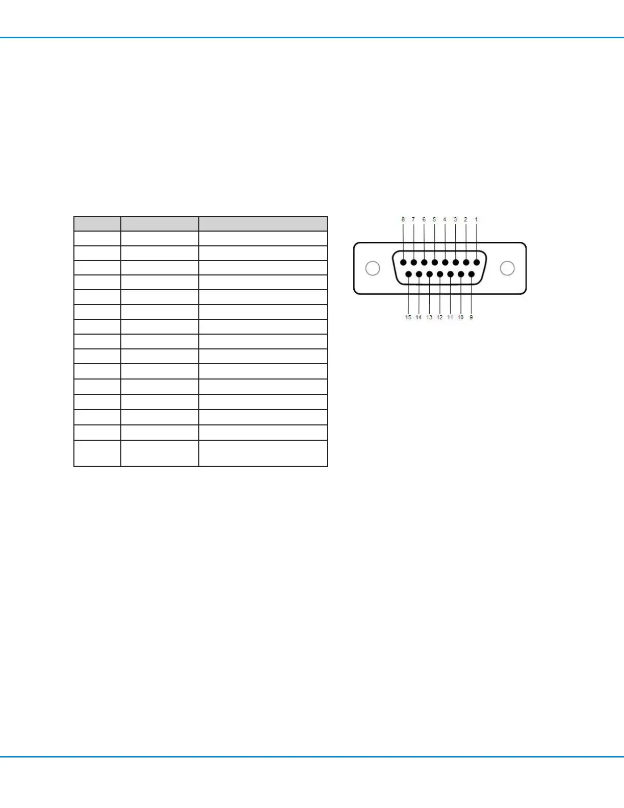
I/O Pin Direction Assignment
1 Input E_Stop (+)
2 Input E_Stop (-)
3 Input Clear_IN (+)
4 Input Clear_IN (-)
5 Input Ex_Trig_IN (+)
6 Input Ex_Trig_IN (-)
7 Output Alarm_OUT
8 Output EOC_OUT
9 Input Contact_Closure (+)
10 Input Contact_Closure (-)
11 Input Program Selector (+)
12 Input Program Selector (-)
13 n/a Not Connected
14 n/a Common
15 n/a +24V_PWR (courtesy +24V
power source)
I/O Port Pin Assignments
If desired, you can connect inputs / output to the I/O port on the back of the controller.
• All outputs are 24 VDC, 100 mA maximum
• Inputs / outputs can use either the courtesy 24VDC power source at pin15 or an external 24VDC source.
Refer to “Input / Output Connections” on page54 for detailed information and wiring diagrams.
UltimusPlus Series Dispensers
53www.nordsonefd.com info@nordsonefd.com +1-401-431-7000 Sales and service of Nordson EFD dispensing systems are available worldwide.

 Loading...


