Input / Output Connections (continued)
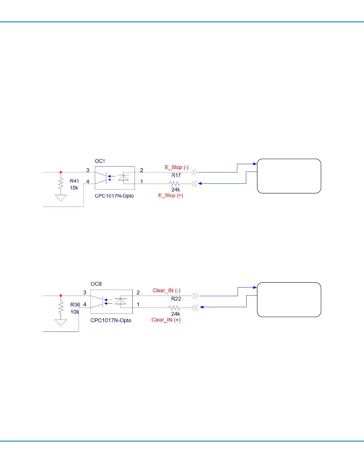
Clear Alarm Circuit
A dispenser alarm or emergency stop can be cleared via I/O from an external source by initiating with a 24 VDC
signal across D-Sub connector pins 3 and 4. The signal can be momentary (no less than 0.1 seconds) or maintained.
Emergency Stop (E-Stop) Circuit
The UltimusPlus dispenser can be emergency stopped via I/O from an external source by initiating a 24 VDC signal
across D-Sub connector pins 1 and 2. The signal can be momentary (no less than 0.1 seconds) or maintained. The
signal will remain in E-stop if held in a high state.
When an E-stop occurs:
• The dispenser stops attempting to regulate pressure
• The output alarm signal from the dispensers goes high
• An red warning box appears on the touchscreen
The dispenser will stay in E-stop mode until either of the following occurs:
• The alarm is cleared by touching (or clicking) anywhere on the touchscreen.
• The Clear Alarm I/O is toggled
-* Common
-* Output 0
-* Output 1
-* Output 2
PC / PLC
DB Pin 2
DB Pin 1
-* Common
-* Output 0
-* Output 1
-* Output 2
PC / PLC
DB Pin 4
DB Pin 3
UltimusPlus Series Dispensers
55www.nordsonefd.com info@nordsonefd.com +1-401-431-7000 Sales and service of Nordson EFD dispensing systems are available worldwide.

 Loading...


