Input / Output Connections
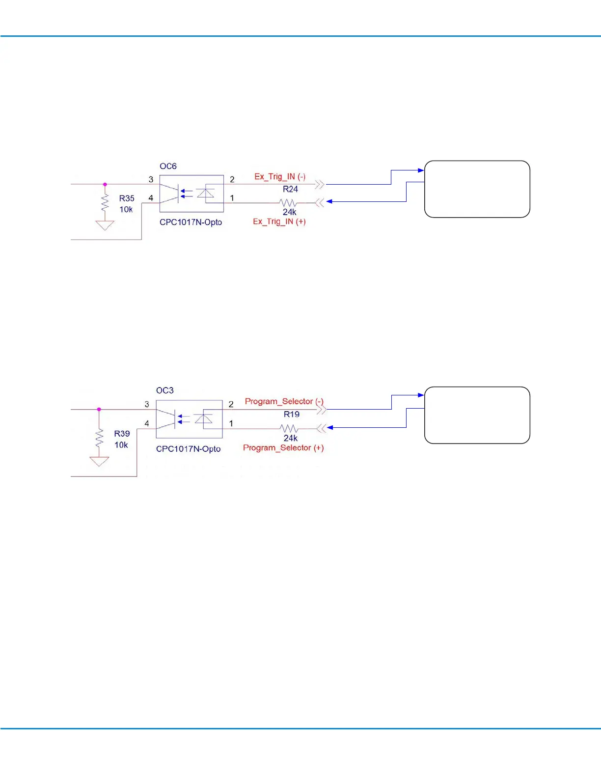
Voltage Initiate Circuit
A dispense cycle can be initiated by a 24 VDC signal across D-Sub connector pins 5 and 6. The signal can be
momentary (no less than 0.01 seconds) or maintained. A new dispense cycle will begin after the signal is removed
and then applied again.
Program Selector Circuit
The active program number can be incremented by initiating a 24 VDC signal across D-Sub connector pins 11 and
12. The signal can be momentary (no less than 0.1 seconds) or maintained. The active program number increments
on each rising edge signal. P1 (Program 1) will change to P2, then to P3, and so on, up to P16. If the program
selector signal is initiated when P16 is the active program, then the active program returns to P1.
-* Common
-* Output 0
-* Output 1
-* Output 2
PC / PLC
DB Pin 6
DB Pin 5
-* Common
-* Output 0
-* Output 1
-* Output 2
PC / PLC
DB Pin 12
DB Pin 11
UltimusPlus Series Dispensers
54 www.nordsonefd.com info@nordsonefd.com +1-401-431-7000 Sales and service of Nordson EFD dispensing systems are available worldwide.

 Loading...


