Parameters for ALL motors
Control panel AND
standard I/O
Alarm: Safety valve open
Fault
Max. in key-to-line
mode
Analog
9.8
Parameters for ALL motors
Line speed
signal
Voltage 0-20 mA
9.8
V
VActual
Max. in key-to-line
mode
10.0
Pump 1
0.0
V
VActual
ON
Coupling broken
monitoring
Operation
4-64
P/N 7105144G
2008 Nordson Corporation
VersaBlue_NW
Motor (contd.)
Motor Parameters
Touch the key to move to the setup screens.
Screen 1: Type of Motor Enable, Adaptation to Parent
Machine
Motor Enable Via Control Panel / Control Panel AND Standard I/O
Control panel: The Standard I/O interface signals All motors ON/OFF
(collective enable) and Enable motor are deactivated. The motors can then
only be enabled and switched on via the control panel.
In this case the melter can function even without a standard I/O connection
to the parent machine, e.g. if it is to be purged for maintenance purposes.
The operator can choose whether an open safety valve generates a fault
(motors are stopped) or a warning.
Enable motor via Control Panel
Fig. 4-88 M2
Line Speed Signal
Either Analog or Frequency can be selected, and either Voltage or Current
can be selected. Depending on what is selected, the keys not used will be
transparent and the units will change. 0−20 mA or 4−20 mA is retrieved
from the I/O board.
NOTE: Voltage or current and 0 − 20 mA or 4 − 20 mA must have been set
on the I/O board with the DIP switches (Refer to section Installation). The
switch setting is read once every time the melter starts up, and it is
displayed on the control panel.
Fig. 4-89 M2.1
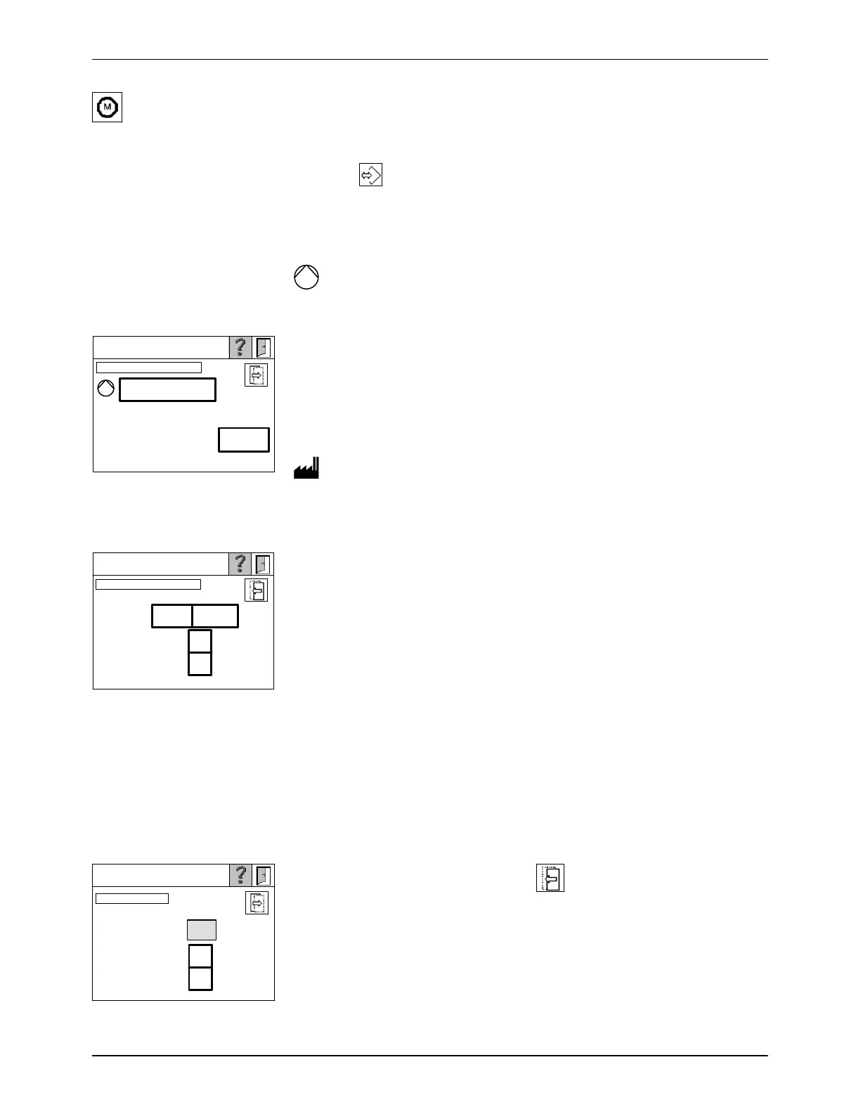
Max. in key-to-line mode
For calibration with the signal (voltage, current or frequency) received from
the parent machine.
Example of operation with pilot voltage: The parent machine runs at
maximum speed. An input signal of 9.8 V (actual value) is displayed. Then
set Max. in key-to-line mode to 9.8.
This screen can also be called up with
of Parameters (Screen 2) when
every motor receives its own line speed signal.
The coupling monitoring function can be switched on and off. It allows faults
in the motor−coupling−pump system to be detected.
Fig. 4-90 M2.2

 Loading...


