+V
-V
E1
E2
E3
E4
E6
E7
E8
E5
+V
E9
+V
E10
+V
E11
E12
+V
+24 V
DC
0 V
DC
24 V
DC
external
A7
A8
A9
A10
A11
A12
A6
A5
A4
A3
A2
A1
+24 V
DC
0 V
DC
0 V
DC
0 V
DC
0 V
DC
+24 V
DC
0 V
DC
Troubleshooting
6-24
P/N 7105144G
2008 Nordson Corporation
VersaBlue_NW
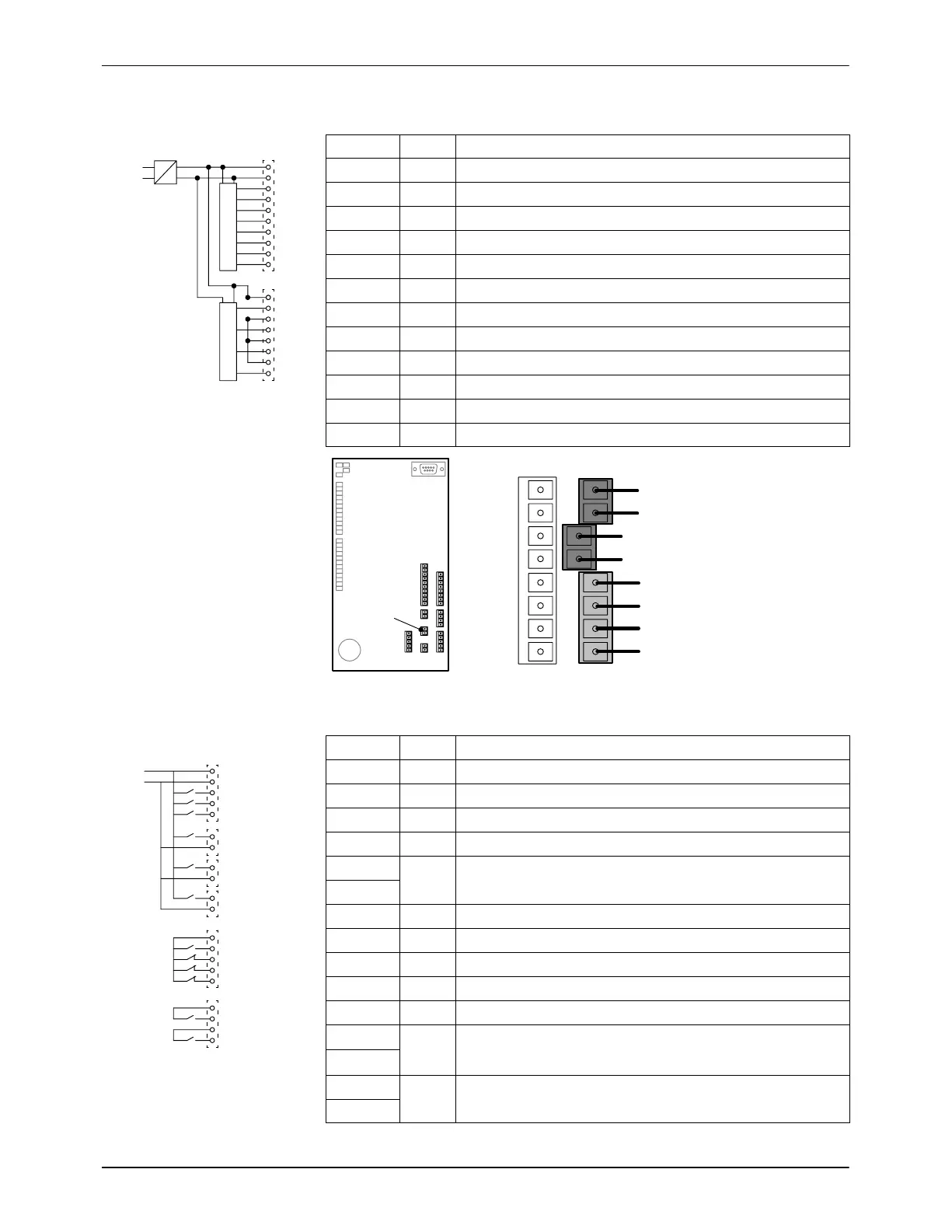
I/O Board #1: Digital Inputs (24 V
DC
)
Plug LED Meaning
X9.3 E1 Heaters on/off
X9.4 E2 All motors on/off (collective enable)
X9.5 E3 Enable Motor 1
X9.6 E4 Enable Motor 2
X9.7 E5 Enter/exit Standby
X9.8 E6 Switch between manual mode / key-to-line
X9.9 E7 Application group 1
X9.10 E8 Application group 2
X13.2 E9 Application group 3
X13.4 E10 Application group 4
X13.6 E11 Main switch (main contactor)
X13.8 E12 Motor circuit switch
X3 X11
X12
X13
X9
X8
X7
X6
X13
1
1
2
3
4
5
6
Split Plug Model
7
8
8
I/O Board #1: Digital Outputs (30 V, 2 A)
Plug LED Meaning
X3.3 A1 Light tower: Green lamp System ready
X3.4 A2 Light tower: Yellow lamp Warning
X3.5 A3 Light tower: Red lamp Fault
X6.1 A4 Main contactor
X7.1 A5 Inert gas control (solenoid valve)
X7.2
X8.1 A6 Pressure build-up completed
X11.2 A7 System ready
X11.3 A8 General alarm −warning−
X11.4 A9 General alarm −fault−
X11.5 A10 Reserved
X12.1
A11 Fill tank
(signal at interface XS2)
X12.2
X12.3
A12 Fill tank
(signal at interface XS3)
X12.4

 Loading...


