+V
-V
E1
E2
E3
E4
E6
E7
E8
E5
+V
E9
+V
E10
+V
E11
E12
+V
+24 V
DC
0 V
DC
24 V
DC
external
A7
A8
A9
A10
A11
A12
A6
A5
A4
A3
A2
A1
+24 V
DC
0 V
DC
0 V
DC
0 V
DC
0 V
DC
+24 V
DC
0 V
DC
Troubleshooting
6-25
P/N 7105144G
2008 Nordson Corporation
VersaBlue_NW
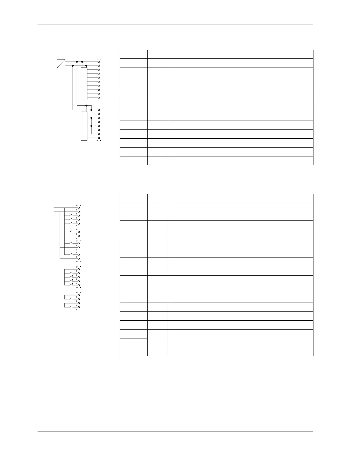
I/O Board #2: Digital Inputs (24 V
DC
)
Plug LED Meaning
X9.3 E1 Enable Motor 3
X9.4 E2 Enable Motor 4
X9.5 E3 Line started / stopped
X9.6 E4 Reserved
X9.7 E5 Safety valve 1
X9.8 E6 Safety valve 2
X9.9 E7 Safety valve 3
X9.10 E8 Safety valve 4
X13.2 E9 Coupling monitoring Motor 1
X13.4 E10 Coupling monitoring Motor 2
X13.6 E11 Coupling monitoring Motor 3
X13.8 E12 Coupling monitoring Motor 4
I/O Board #2: Digital Outputs (30 V, 2 A)
Plug LED Meaning
X3.3 A1 Reserved
X3.4 A2 Reserved
X3.5 A3 Pneumatic pressure control valve 1
or 1 and 2 with double-stream pumps
X6.1 A4 Pneumatic pressure control valve 2
or 3 and 4 with double-stream pumps
X7.1 A5 Pneumatic pressure control valve 3
or 5 and 6 with double-stream pumps
X8.1 A6 Pneumatic pressure control valve 4
or 7 and 8 with double-stream pumps
X11.2 A7 Reserved
X11.3 A8 Reserved
X11.4 A9 Reserved
X11.5 A10 Reserved
X12.1 A11 Pressure buildup completed
X12.2
X12.3 A12 Reserved

 Loading...


