DAP deployment rules and requirements 39
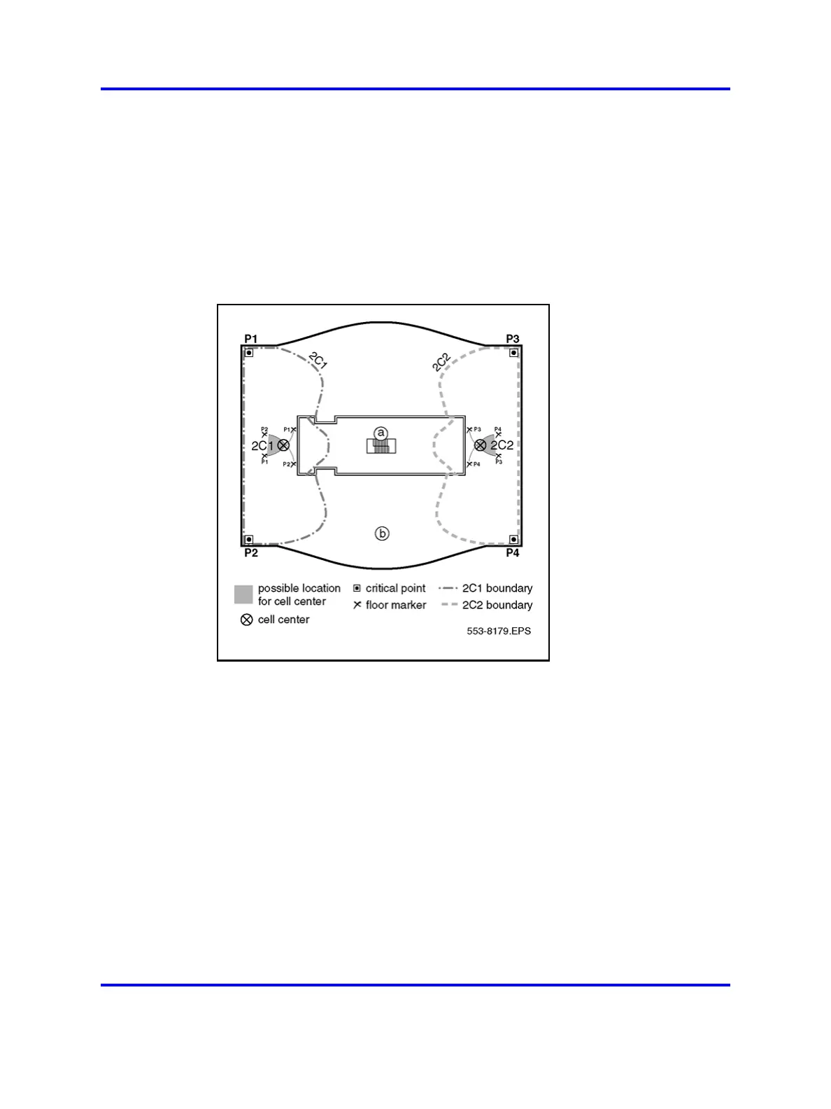
Figure 11 "Cell boundaries" (page 39) shows the following.
A cell boundary for the cell center is determined by placing the deployment
tool at the cell center, for example 2C1, and using the deployment handset
to establish the cell boundary. The cell boundary contour is marked on
the floor plan, and shown in Figure 11 "Cell boundaries" (page 39) by a
dash-dot line.
Figure 11
Cell boundaries
Identify critical points and cell boundaries
Figure 12 "Additional critical points and cell boundaries" (page 40) shows
the following.
• stairwell
• second floor plan
Additional critical points, shown in Figure 12 "Additional critical points and
cell boundaries" (page 40) as P5, P6, P7, and P8, are identified to ensure
basestation radio coverage for the entire area.
Nortel Communication Server 1000
SIP DECT Fundamentals
NN43120-123 01.07
6 January 2009
Copyright © 2008-2009 Nortel Networks
.
 Loading...