78 Site planning
10 Mark each cell center on the floor plan and label them 1C1 and
1C2.
11 Place the deployment tool at each cell center.
12 Locate the cell boundary and mark it on the floor plan. (Mark
the contours in different colors for easy differentiation of cell
centers.)
13 Define and mark on the plan subsequent critical points, where
each cell boundary crosses the edge of the coverage area.
14 If the cell boundary covers other critical points, ignore these
critical points as you proceed with coverage deploying.
15 Repeat the multi cell technique for the remaining area to be
covered, from the extremes of the coverage area toward the
center, until all of the floor is covered.
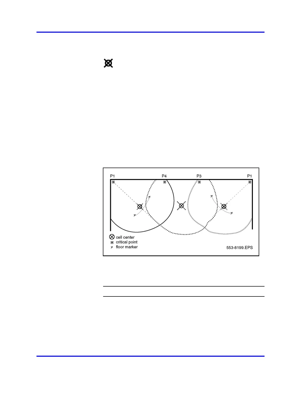
Figure 46
Multi cell distance using the single cell technique
16 Use the subsequent critical points to fill in the coverage area
between the first two cells using the “Single-cell deployment”
(page 73). An example of this is shown in Figure 46 "Multi cell
distance using the single cell technique" (page 78).
--End--
Multiple floor deployment
This applies to deployment scenarios in the following situations.
• The coverage area is on more than one floor.
• The floors are not adjacent to each other.
Nortel Communication Server 1000
SIP DECT Fundamentals
NN43120-123 01.07
6 January 2009
Copyright © 2008-2009 Nortel Networks
.
 Loading...