Oki Data CONFIDENTIAL
45487001TH Rev.1
4-23 /
4. Maintenance menus
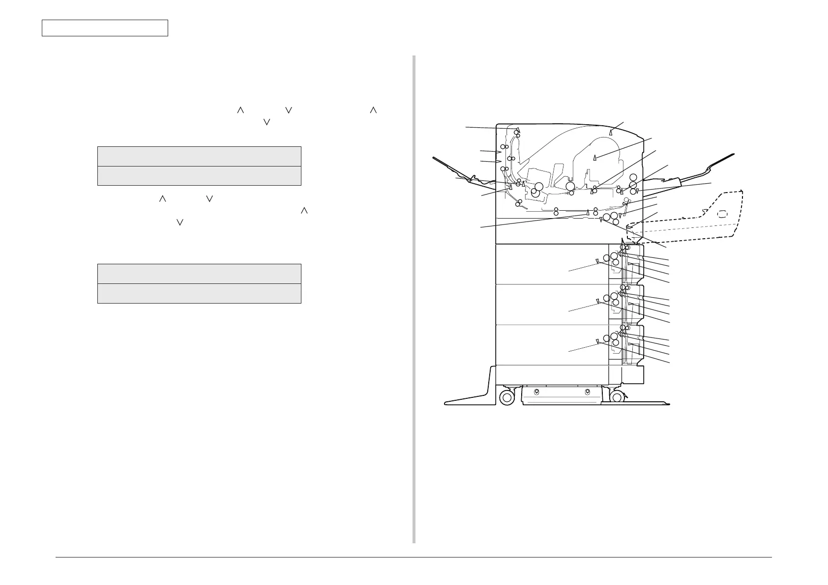
Figure 4-1 Switch sensor locations
4.3.2.3 Switch scan test
The switch scan test is used for checking entrance sensors and switches.
1. Enter the self-diagnostic mode (level 1) and, until SWITCH SCAN appears on
the upper display, press the MENU
or MENU
button (the MENU
button
displays the next test option and the MENU
button displays the preceding test
option). Then press the ENTER button.
SWITCH SCAN
2. Press the MENU
or MENU button until an option shown in table 4-3 for the
unit to test appears on the lower display (the MENU
button displays the next
option and the MENU
button displays the preceding option).
3. Press the ENTER button. The switch scan test starts, the unit’s name and
current status being displayed
PAPER ROUTE:PU
1=H 2=L 3=H 4=L
Operate the unit (figure 4-1). Display information on applicable LCD display (the
information displayed vary depending on the sensor.
4. Press the CANCEL button. The state in step 2 is restored.
5. Repeat steps 2 through 4 when necessary.
6. Press the BACK button to end the test (the state in step 1 is restored.
1stSIZESW
INSNS1
HOPSNS
MPTPE SW orSNS
PESNS
DUPF SNS
2nd INSNS
2nd HOPSNS
2nd SIZESW
PESNS
3rd INSNS
3rd HOPSNS
3rd SIZESW
PESNS
4th INSNS
4th HOPSNS
4th SIZESW
PESNS
DUPIN SNS
FU SW
REAR SNS
STKSNS
EXIT SNS
TNRSNS
WR2SNS
INSNS2