Oki Data CONFIDENTIAL
45487001TH Rev.1
6-60 /
6. Troubleshooting procedure
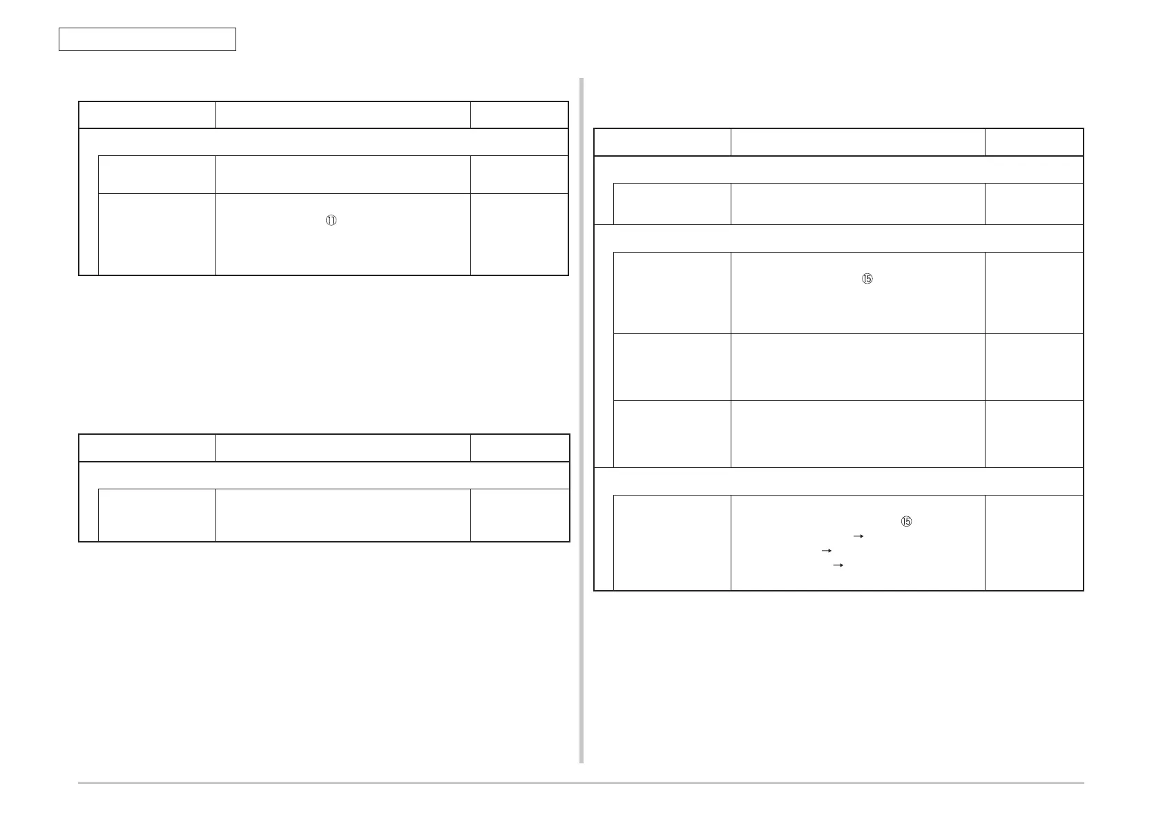
(11-3) All fans of the printer do not rotate.
Check item Check work
Actions to be taken
at NG
(11-3-1) 24V power supply
PU/CU board fuses
F1, F503
Check if the fuses F1 is not open-circuit or
not.
Replace the
PU/CU board.
24V power that is
supplied to the PU/
CU board.
Check the power supply voltages at the
POWER connector
of the PU/CU board.
The follow voltage must appear respectively.
Pins-17, -18, -19, -20, -21: 0VP
Pins-11, -13, -14, -15, -16: 24V
Replace the low
voltage power
supply.
6.5.2.(12) Print speed is slow. (Performance is low.)
(12-1) Print speed decreases.
Check item Check work
Actions to be taken
at NG
(12-1-2) Media Weight setting
Media Weight that
is specified for the
print
Check if the wrong Media Weight has been
specified or not.
Correct the
Media Weight.
6.5.2.(13) Option Unit cannot be recognized.
(13-1) Option try unit cannot be recognized.
Check item Check work
Actions to be taken
at NG
(13-2-1) Option try board
Option try unit Check if the option try unit specification is
being used or not.
Replace the
option tray unit.
(13-1-2) Check the system connection
Check the system
connection from the
PU/CU board to the
option tray board
(GOH-12 PCB).
Check that the cable between the PU/CU
board option connector
to the option tray
board is normally connected.
Correct the
connections.
Square connector
connecting the
option tray unit to
the printer.
Check if any foreign material exists in the
connecting portion of the square connector.
Remove
the foreign
material.
Square connector
connecting the
option tray unit to
the printer.
Is the terminals of the square connector
damaged?
Replace the
connector.
(13-2-3) Check the control signals.
Check the control
signal that is output
from the PU/CU
board to the option
tray board (GOH-12
PCB).
Check the control signal that is output from
the PU board option connector
.
Pin-8: OPTCNT2 (PU
2nd)
Pin-9: TXD (PU
2nd)
Pin-10: RXD (2nd
PU)
Pin-9: Replace
the PU/CU
board.
Pin-10: Replace
the option tray
board.