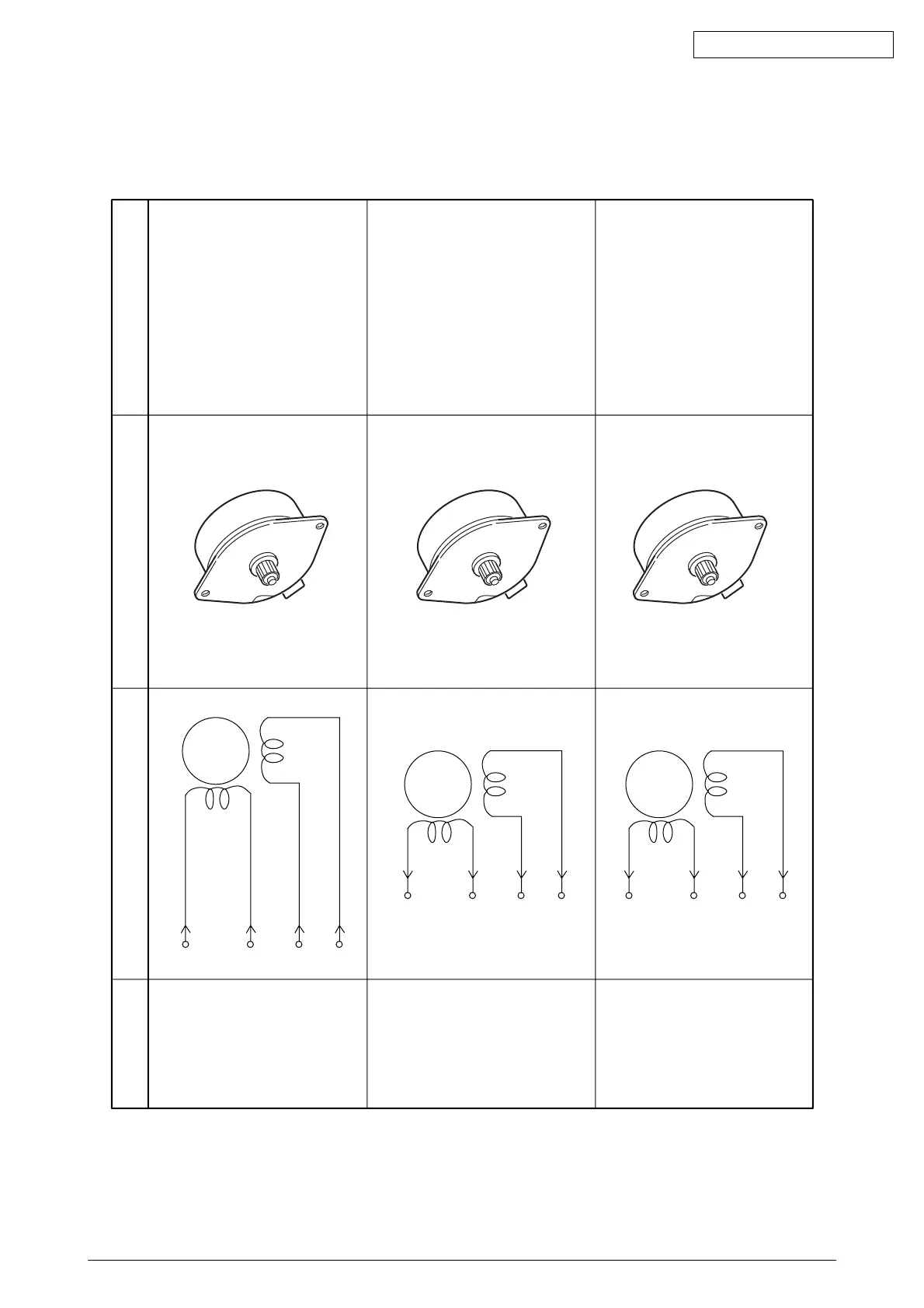
8. CONNECTION DIAGRAM
Unit Circuit Diagram Illustration Resistance
Between pins 1 and 2: 3.5
Ω
Between pins 3 and 4: 3.5
Ω
Between pins 1 and 2: 3.4
Ω
Between pins 3 and 4: 3.4
Ω
or
Between pins 1 and 2: 5
Ω
Between pins 3 and 4: 5
Ω
Between pins 1 and 2: 3.4
Ω
Between pins 3 and 4: 3.4
Ω
or
Between pins 1 and 2: 5
Ω
Between pins 3 and 4: 5
Ω
Transport Belt Motor
Main Motor (Y)
Main Motor (M)
Red
Brawn
Yellow
Blue
M
1
2
3
4
M
1
2
3
4
M
1
2
3
4