42615101TH Rev.8 94 /
Oki Data CONFIDENTIAL
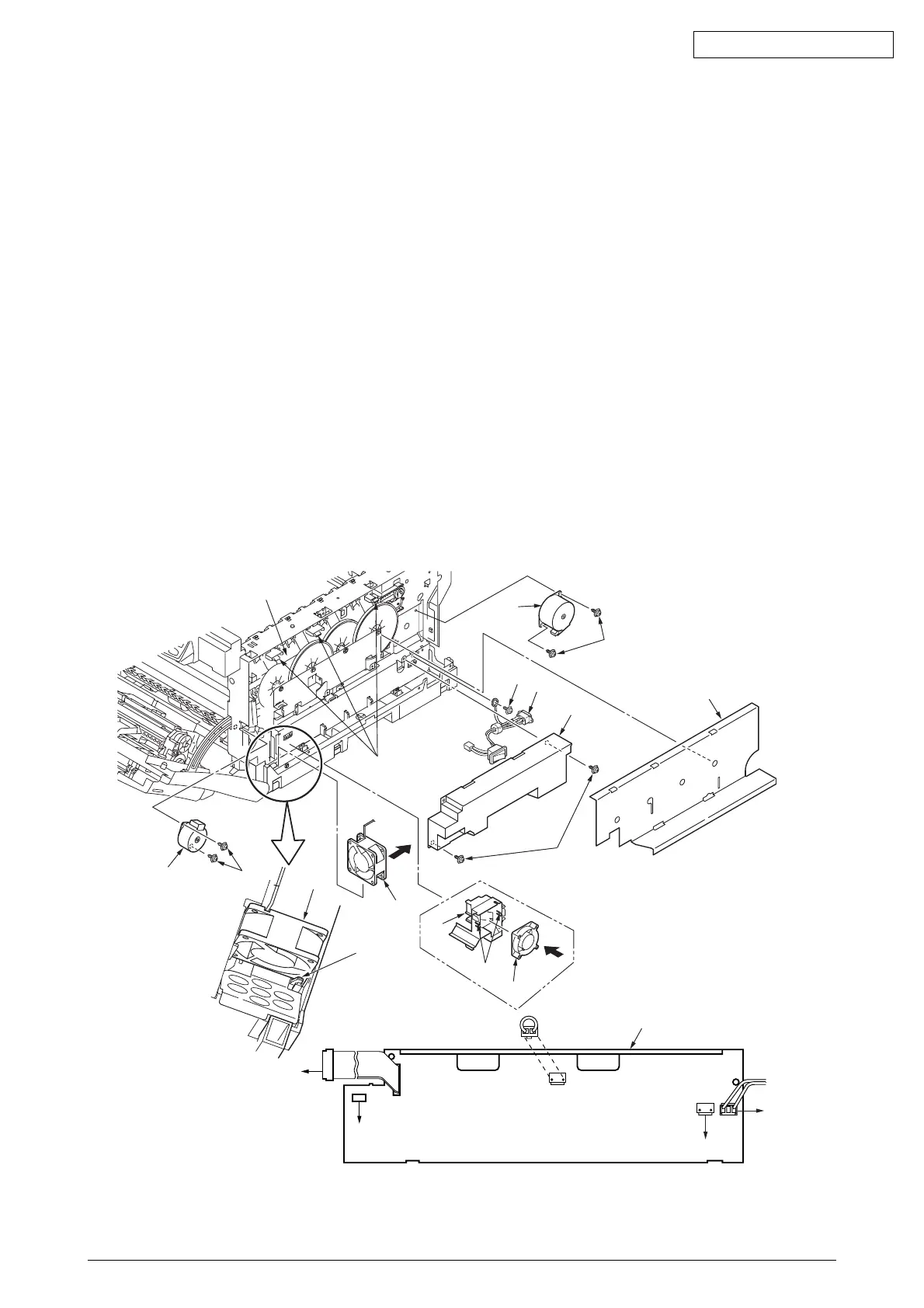
4.2.12 Low-Voltage Power Unit / ID-FAN / Low-Voltage Power Unit FAN /
Hopping Motor / Fuser Motor
(1) Remove the print controller PCB (see section 4.2.7).
(2) Remove the controller PCB (see section 4.2.6).
(3) Boost up the three claws A of the Guide Assy Side R 1 to remove the film 2 and
the Frame-Duct 3. Remove the two claws B of Duct 3 to demount the ID-FAN 4.
(4) Remove the two screws (golden) 5 and the four connectors (CN2, CN3, CN4, CN6) to
demount the Low-voltage Power Unit 6 (Tool No.1). Remove the screw B to detach the
AC Inlet Assy C.
(5) Demount the Low-voltage Power Unit FAN 7 by releasing the claw C.
(6) Remove the two screws (black) 8 and the connector to detach the hopping motor 9 (Tool No.1).
(7) Remove the two screws (black) 0 and the connector to detach the fuser motor A (Tool No.1).
Note!
• When reassembling the ID FAN 4, Low-voltage Power Unit FAN 7, check the
attachment direction.
• When reassembling the Low-voltage Power Unit6, check the setting of AC input voltage.
100V series: Install a short plug to the connector CN5
230V series: Do not install a short plug to the connector CN5
• The Low-voltage Power Unit 6 and the AC Inlet Assy C must be replaced in a pair
(they were in a pair qualified to applicable safety standards).
Figure 4-2-12
Low-voltage Power Unit / ID-FAN / Low-Voltage Power Unit FAN / Hopping Motor / Fuser Motor
Claw C
Claw B
4
B
C
6
Low-voltage
power supply board
Short plug
for CN5
I/F connector of the fuser unit
Note) CN5: Connector to switch over the setting of AC input voltage
100V series: A short plug is installed. / 230V series: A short plug is not installed.
AC
switch
Low-voltage Power Unit FAN7
PRN PCB
POWER
connector
CN6
CN2
CN5
CN4
CN3
1
Claw A