45376001TH Rev.1
136 /
Oki Data CONFIDENTIAL
5. Maintenance Menu
section 2.4.1.1.10.4)
When the board is replace with the new board, the new board has been set
in the Factory working mode. Therefore, it should be switched to the Shipping
mode.
setting function” – section “2.4.1.1.10.4 Factory/Shipping mode” screen.
Note! Note that replacing the PU board with a new one without copying
information onto the new one from the board’s EEPROM clears information
about the lives of units of the printer, including the belt, toner and image
drums, causing errors in managing these lives on the printer until the units
are replaced. The counts cleared with such PU board replacement are as
shown in the list below and chapter 2 Counter Specifications. When the
units are replaced with new ones, their respective counts except for Total
Sheets Fed are cleared, the errors being corrected.
Item Contents Count contents
Fuser unit Fuser unit life count Number of print copies after
the new fuser unit is installed,
after the data is converted to
equivalent number of A4 size
paper counts.
Belt unit Belt unit life count Number of print copies after
the new belt unit is installed,
after the data is converted to
equivalent number of A4 size
paper counts.
ID unit : Black
ID unit : Yellow
ID unit : Magenta
ID unit : Cyan
Life count of respective
ID units
Number of print copies after the
new ID unit is installed, after the
data is converted to equivalent
number of A4 size paper counts.
Total number of papers
fed
Printer life count Total number of papers fed
Print : Black
Print : Yellow
Print : Magenta
Print : Cyan
Number of print copies
of each ID
Number of print copies after the
new ID unit is installed.
2. When access to the EEPROM of the board to remove is impossible.
If the SERVICE CALL 104 [Engine EEPROM Error] is displayed on the operator
panel with the board to remove, or is EEPROM data cannot be read-out, perform
the following procedure by using the Maintenance Utilities.
(1) Setting the serial number information (Maintenance Utilities Operation
Manual section 2.4.1.1.10.3)
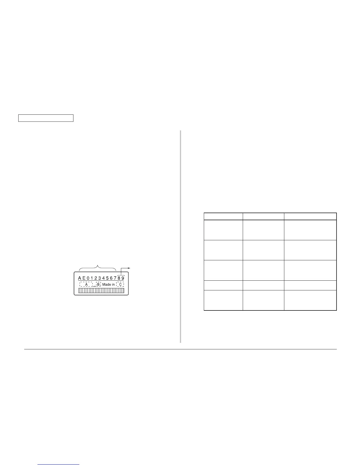
The SAP serial number is applied to printer. The SAP serial number is
displayed in the top-most row of the serial number label. Its number indicates
the production place with 2 digits, manufacture date with 2 digits, serial
number (sequential number) with 6 digits and revision number with 2 digits
totaling 12 digits number.
Number for the output mode.
digits among the 12 digits SAP serial number.
Board setting function” – section “2.4.1.1.10.3 Serial number information setting”.
in single-byte character) at the top. (Be careful that the read-out data shows the 10
digits number.)
Enter the 11 digit number by adding “0” (Zero in single-byte character) before the
10 digit number excluding the revision 2 digits that is shown in conceptual drawing
of “Serial number information setting” screen as shown below.
Configuration. Therefore, confirmation upon completion of rewriting the PU serial
number can be performed by printing the Configuration.
(2) Switching to the Shipping mode (Maintenance Utilities Operation Manual