45376001TH Rev.1
77 /
Oki Data CONFIDENTIAL
4. Component replacement
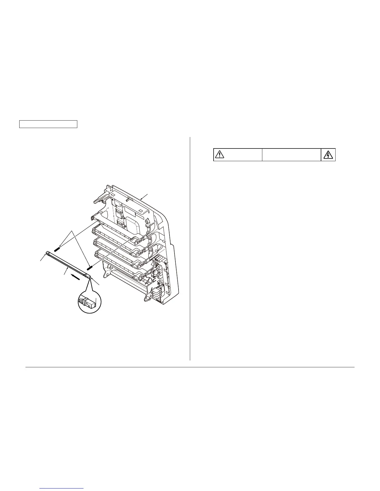
4.2.8 LED Assy/ LED Assy spring
(1) Open the scanner and top cover.
(2) After removing the cable, as shown in fig 2, push the LED assy
①
tightly in the
direction of arrow. Take the hook A out firstly, and then take the hook B out, at
last remove the LED assy.
(At this time, the two springs
②
is removed with LED Assy
①
.)
4.2.9 CU/PU PCB/Low voltage power supply
Top cover
Hook B
Hook A
Hook A
Figure (1)
Figure (2)
①
②
Risk of Electric Shock
There is a risk of electric shock during replacement of the low voltage power
supply.
Use insulating gloves or avoid direct contact with any conducting part of the
power supply, and caution should be exercised during replacement.
The capacitor may take one minute to complete discharge after the AC cord
is unplugged. Also, there is a possibility that the capacitor doesn’t discharge
because of a breakage of the PCB, etc., so remember the possibility of
electric shock to avoid electric shock.
(1) Open the scanner and top cover.
(2) Remove the right side cover. (See section 4.2.3)
(3) Remove the eight screws (silver,No:42920406)
①
to take the plate-shield
②
out.
(4) Remove the four screws (silver,No:42920406)
③
and all cables, and take the the
FAX PCB
④
out.
(5) Remove the eight screws (silver,No:42920406)
⑤
and all cables, and take the
CU PCB
⑥
out.
(6) Remove the two screws (silver,No:42920406)
⑦
and all cables, and take the PU
PCB
⑧
and Film Board
⑨
out.
(7) Remove the two screws (silver,No:42920406)
⑩
and all cables, and take the
Low voltage power supply
⑪
out.
Note!
side-R, preventing from touching the edge of the plate-side-R.
⑪
and AC Inlet Assy
should be replaced together.
(The pair of low-voltage power supply and AC Inlet Assy meets the
safety standards.)