45376001TH Rev.1
38 /
Oki Data CONFIDENTIAL
2. Operating instructions
2.3 Image Scanning process
2.3.1 Structure and process of RADF
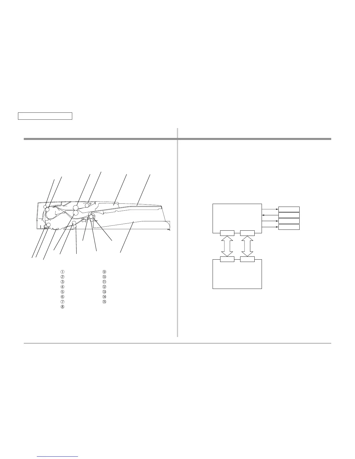
2.3.1.1 Cross-section view
䐟䐠䐢
䐡
䐤
䐥
䐮
䐭
䐫
䐬
䐪䐩
䐣
䐨
䐦䐧
Paper tray Pressure roller
Paper guide Paper holder
Pick-up roller Scan roller
Feed roller Pinch roller
Retard roller Exit roller
Transfer roller Upper pinch roller
Pinch roller Lower pinch roller
Regist roller
⑯
Paper stocker
2.3.1.2 Electrical configuration
Electrical circuit configuration
This Scanner is controlled by the SU board(7SU).
The ASIC mounted on the SU board(7SU) control the DC load devices such as motor,
solenoid and clutch via the ADF Relation board(7RL), in dependance of the sensor signals
and control signals from the CU board not to be shown in the below figure.
Motor
MOTIF
ADF Relation board
(7RL)
SU board
(7SU)
+24V +3.3V
ADFM
SNSIF
ADFS
Sensor
Solenoid
Clutch