OMNI 4000/7000 Installation Guide – Rev H
3.5 OMNI 4000/7000 Back Panel Terminal Blocks
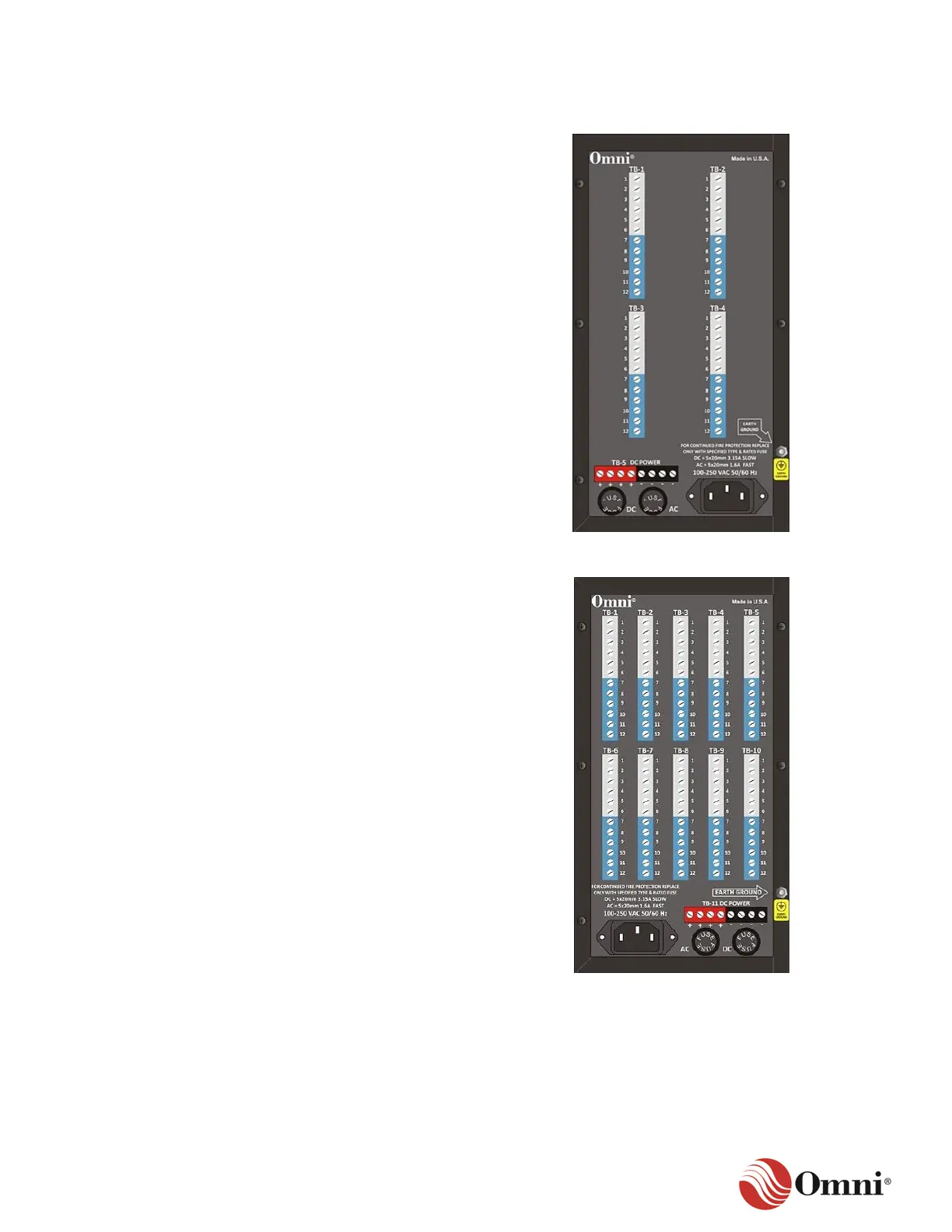
The OMNI 4000 standard and extended back
panel is illustrated in Figure 3-14.
• Terminal blocks TB-1 through TB-4 provide
signal I/O terminations.
• The terminals for each terminal block,
which are labeled 1 through 12, provide
48 circuit paths.
• Each terminal block corresponds to an
I/O module slot on the motherboard.
• TB-5 provides DC power to various field
devices when the flow computer is powered
with AC.
Go to Section 8 for the electrical specifications
of the back panel, such as the transducer
output power.
Figure 3-14: OMNI 4000 Back Panel
The OMNI 7000 standard back panel is
illustrated in Figure 3-15.
• Terminal blocks TB-1 through TB-10
provide signal I/O terminations.
• The terminals for each terminal block,
which are labeled 1 through 12, provide
120 circuit paths to the motherboard.
• Each terminal block corresponds to an
I/O module slot on the motherboard.
• TB-11 provides DC power to various field
devices when the flow computer is powered
with AC.
Go to Section 8 for the electrical specifications
of the back panel, such as the transducer
output power.
Figure 3-15: OMNI 7000 Standard Back
Panel
 Loading...