3.7.2 Digital I/O Terminal Board
The Digital I/O Terminal (DT) board communicates with the DM module to provide 16 additional
digital inputs or outputs to the flow computer.
Each Digital I/O point may be independently configured as an input or output through
OMNICONNECT software. All digital points are referenced to the DC return of the DT board.
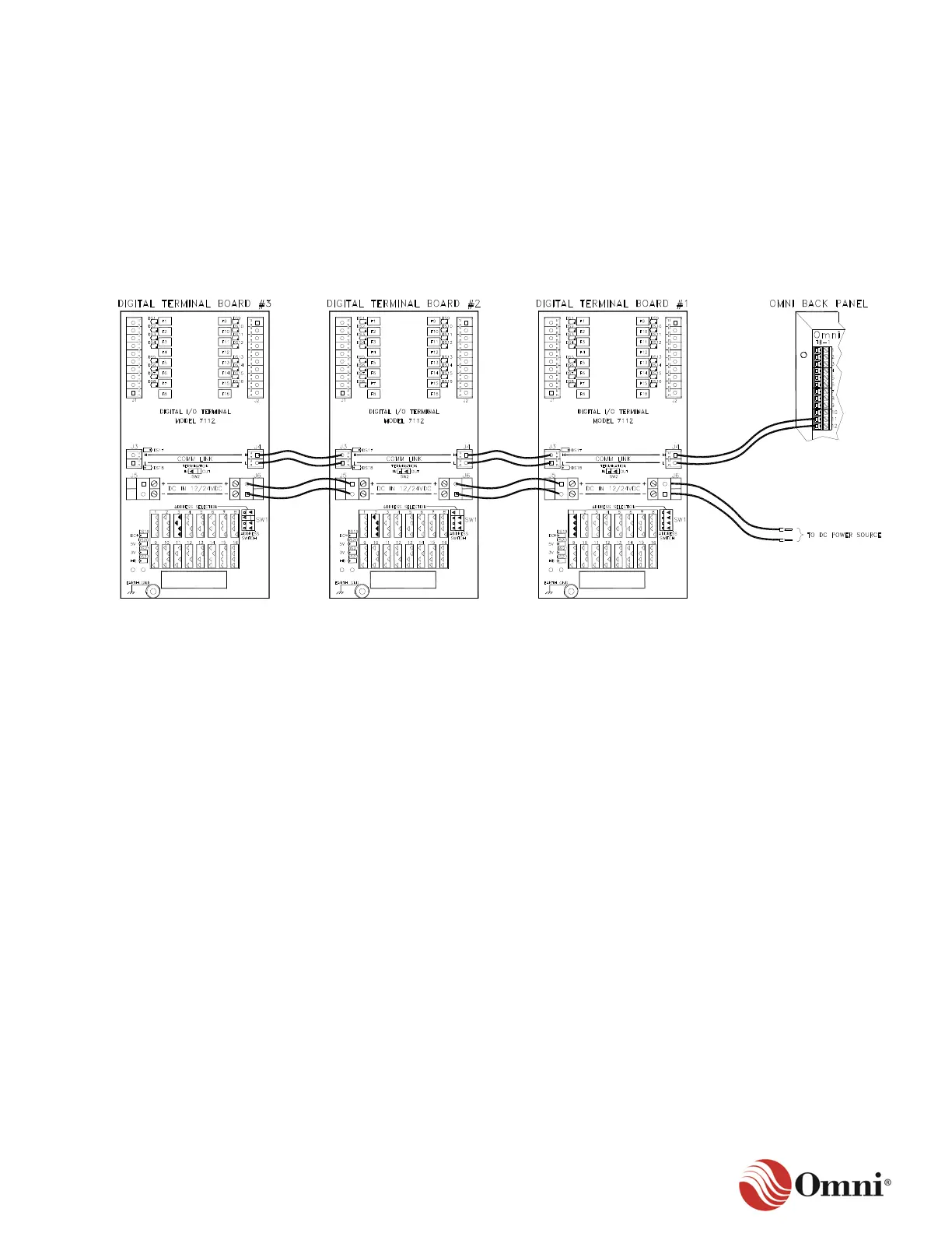
Figure 3-20 illustrates a wiring connection example for the DT board. Always use your project
specific drawings for wiring the DT Board.
Figure 3-20: Example DT Board Wiring
In this example:
• J1 and J2 provide the 16 additional field device inputs or outputs.
• J3 provides the communications connection to a second DT board.
• J4 provides the communications connection to the flow computer back panel.
• J5 connects the power source to the second board.
• J6 connects to a DC power source.
This configuration allows for a series of DT boards that provide additional inputs and outputs.
 Loading...