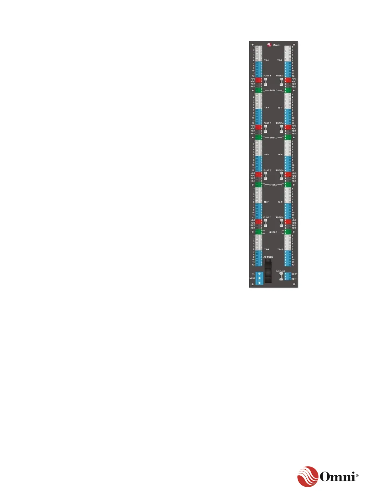
The OMNI 7000 extended back panel is
illustrated in Figure 3-16.
• Terminal blocks TB-1 through TB-10
provide signal I/O terminations.
• The terminals on each terminal block
provide the same number of circuit paths
as the OMNI 7000 standard back panel.
• TB-1 through TB-8 contain extra terminals
to provide DC power to various field
devices when the flow computer is powered
with AC. The terminals include:
− DC+ power with fuses.
− DC return.
− Shield connections.
• Screw-type terminals on the lower right and
left provide AC and DC input power.
Go to Section 8 for the electrical specifications
of the back panel, such as the transducer
output power.
3.6 Input and Output Modules Overview
The OMNI 4000/7000 flow computer functions by using the following I/O module types:
• Digital I/O Multiplexer (DM)
• Serial (S)
• Dual Ethernet (DE)
• Process I/O
The DM module provides inputs and outputs to control provers, samplers and injection pumps to
provide remote totalizing.
The S or DE modules provide Ethernet and serial ports to communicate with devices such as
printers, PCs, SCADA networks or other flow computers.
Process I/O modules provide the input and output of process measuring devices, such as
temperature and pressure transducers, densitometers, flow meters and provers.
 Loading...