OMNI 4000/7000 Installation Guide – Rev H
CAUTION: If the order of the modules in the chassis is modified, the configuration no
longer matches the standard drawings provided. The wiring to the terminal blocks will
need to be modified, and your project-specific drawings and documentation will need
to be revised.
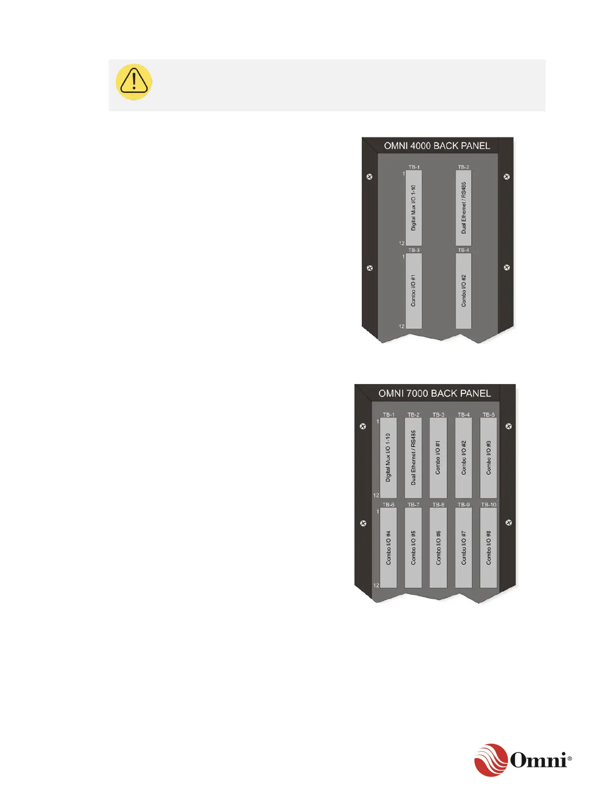
Figure 3-17 illustrates the standard factory
order of the I/O modules in relation to the
terminal blocks on the OMNI 4000 back panel:
• The TB-1 terminal block is used for the DM
module.
• The TB-2 terminal block is used for a
communication module.
• TB-3 and TB-4 are used for Process I/O
modules.
• Each terminal block corresponds to an I/O
module slot on the motherboard.
Figure 3-17: I/O Modules and the
OMNI 4000 Back Panel
Figure 3-18 illustrates the standard factory
order of the I/O modules in relation to the
terminal blocks on the OMNI 7000 back panel:
• The TB-1 terminal block is used for the
DM module.
• The TB-2 through TB-4 terminal blocks are
used for DE modules or S modules (RS485
in this example), depending on the number
of communication modules needed.
• The process I/O modules typically start
from TB-3 to TB-5, depending on the
number of communication modules. These
modules vary in number, depending on
project requirements.
• Each terminal block corresponds to an I/O
module slot on the motherboard.
Figure 3-18: I/O Modules and the
OMNI 7000 Back Panel
 Loading...