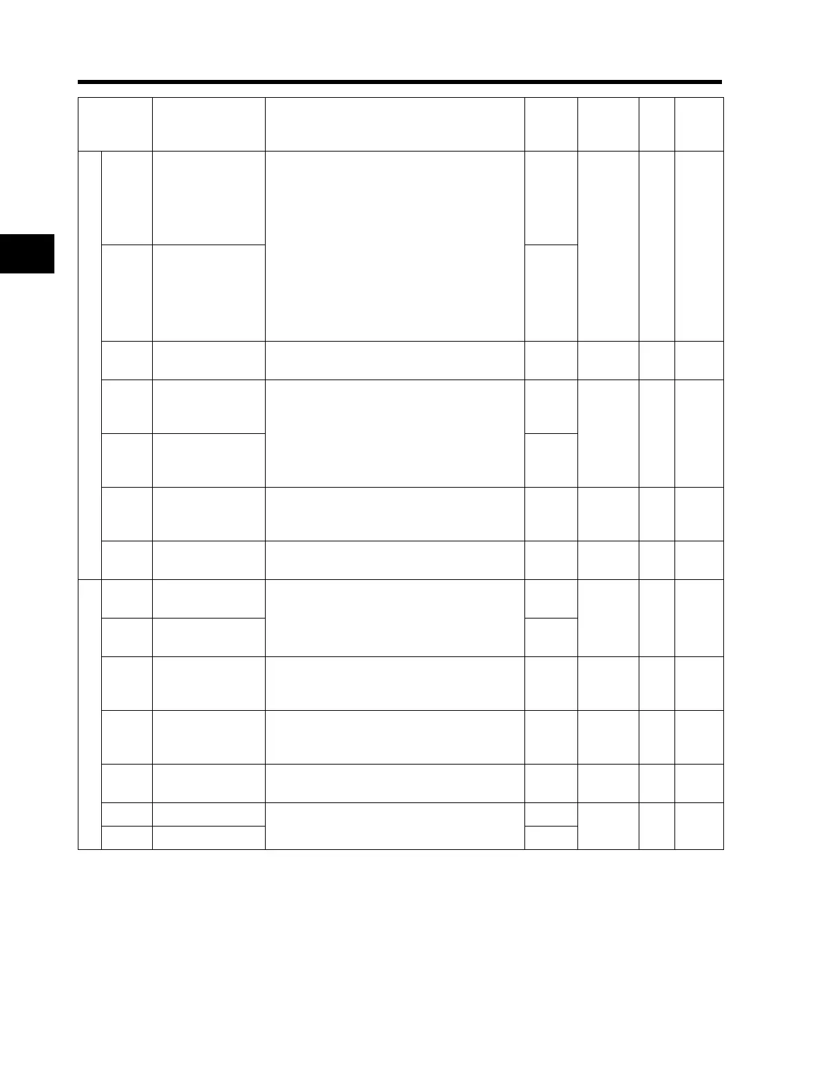
3-33
3-7 Parameter List
3
Operation
Multi-function output setting
C021
Multi-function
output terminal P1
selection
00: RUN (signal during RUN)
01: FA1 (constant speed arrival signal)
02: FA2 (over set frequency arrival signal)
03: OL (overload warning)
04: OD (excessive PID deviation)
05: AL (alarm output)
06: Dc (disconnection detection)
07: FBV (PID FB status output)
08: NDc (network error)
09: LOG(logic operation output)
10: ODc (Do not use.)
43: LOC (light load detection signal)
00
No ⎯ 4-62
C026
Relay output (MA,
MB) function
selection
05
C028 AM selection
00: Output frequency
01: Output current
00 No ⎯
4-35
4-75
C031
Multi-function
output terminal P1
contact selection
00: NO contact at MA; NC contact at MB
01: NC contact at MA; NO contact at MB
00
No ⎯ 4-71
C036
Relay output (MA,
MB) contact
selection
01
C038
Light load signal
output mode
00: Enabled during acceleration/deceleration/
constant speed
01: Enabled only during constant speed
01 No ⎯ 4-70
C039
Light load
detection level
0.0 to 2.0 × Rated current (0.0 setting:
Function disable)
Rated
current
No ⎯ 4-70
Level output status setting
C041
Overload warning
level
0.0: Does not operate
0.1 × Rated current to 2.0 × Rated current
Rated
current
No A
4-31
4-65
C241
*2nd overload
warning level
Rated
current
C042
Arrival frequency
during
acceleration
0.0 to 400.0 0.0 No Hz 4-64
C043
Arrival frequency
during
deceleration
0.0 to 400.0 0.0 No Hz 4-64
C044
PID deviation
excessive level
0.0 to 100.0 3.0 No %
4-20
4-65
C052 PID FB upper limit
0.0 to 100.0
100
No % 4-20
C053 PID FB lower limit 0.0
Parameter
No.
Function name
Monitor or data range
(Digital Operator)
Default
setting
Changes
during
operation
Unit Page
* 2nd control is displayed when SET (08) is allocated to one of from C001 to C005.