4-14
4-2 Wiring
Accurax G5 AC SERVOMOTOR AND SERVO DRIVE USER'S MANUAL
4
System Design
Main Circuit and Motor Connections
When wiring the main circuit, use proper wire sizes, grounding systems, and noise resistance.
R88D-KTA5L/-KT01L/-KT02L/-KT04L
R88D-KT01H/-KT02H/-KT04H/-KT08H/-KT10H/-KT15H
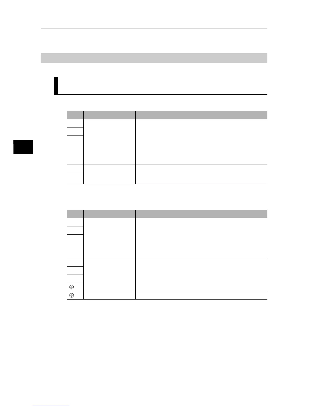
Main Circuit Connector Specifications (CNA)
Motor Connector Specifications (CNB)
Symbol
Name Function
L1
Main circuit power supply
input
R88D-KTxL
(50 to 400 W) : Single-phase 100 to 115 VAC (85 to 127 V) 50/60 Hz
(200 to 400 W): 3-phase 100 to 115 VAC (85 to 127 V) 50/60 Hz
R88D-KTxH
(100 W to 1.5 kW) : Single-phase 200 to 240 VAC (170 to 264 V)
50/60 Hz
(100 W to 1.5 kW): 3-phase 200 to 240 VAC (170 to 264 V) 50/60
Hz
L2
L3
L1C
Control circuit power
supply input
R88D-KTxL : Single-phase 100 to 115 VAC (85 to 127 V) 50/60Hz
R88D-KTxH : Single-phase 200 to 240 VAC (170 to 264 V) 50/60
Hz
L2C
Symbol
Name Function
B1
External Regeneration
Resistor connection
terminals
50 to 400 W: These terminals normally do not need to be
connected. If there is high regenerative energy, connect an
External Regeneration Resistor between B1 and B2.
750 W to 1.5 kW: Normally B2 and B3 are shorted. If there is high
regenerative energy, remove the short-circuit bar between B2 and
B3 and connect an External Regeneration Resistor between B1
and B2.
B2
B3
U
Motor connection
terminals
These are the output terminals to the Servomotor.
Be sure to wire them correctly.
V
W
Frame ground This is the ground terminal. Ground to 100 Ω or less.

 Loading...