364
Command and Response Formats Section 6-2
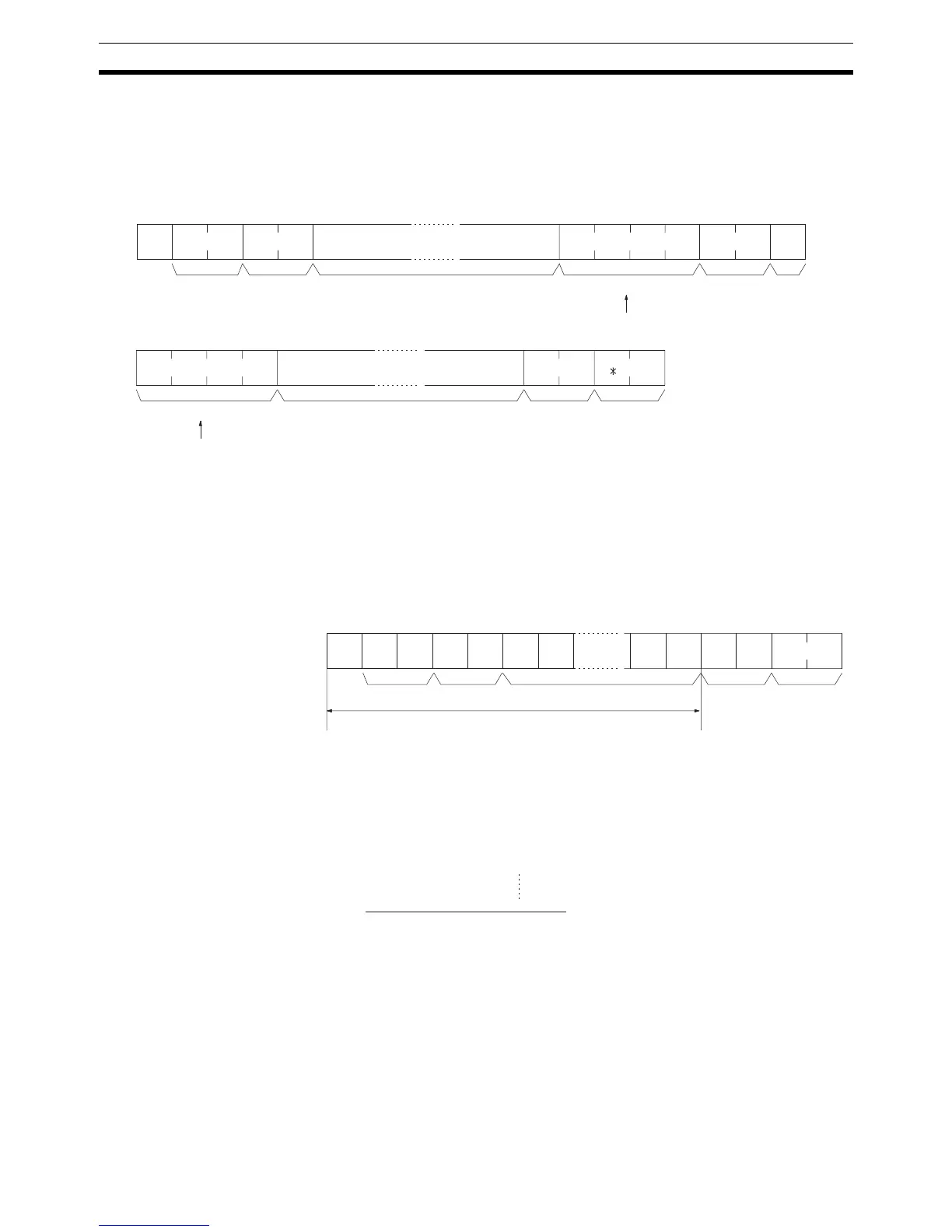
Precautions for Long Transmissions
When dividing commands such as WR, WL, WC, or WD that execute write
operations, be careful not to divide into separate frames data that is to be writ-
ten into a single word. As shown in the illustration below, be sure to divide
frames so that they coincide with the divisions between words.
FCS (Frame Check
Sequence)
When a frame is transmitted, an FCS is placed just before the delimiter or ter-
minator in order to check whether any data error has been generated. The
FCS is 8-bit data converted into two ASCII characters. The 8-bit data is the
result of an EXCLUSIVE OR performed on the data from the beginning of the
frame until the end of the text in that frame (i.e., just before the FCS). Calcu-
lating the FCS each time a frame is received and checking the result against
the FCS that is included in the frame makes it possible to check for data errors
in the frame.
@
↵
00WD
FCS
↵
Frame 1
Node
no.
Header
code
Data
One word of data
Data from the same word is not divided.
Frame 3
Terminator
Data
Delimiter
One word of data
Data from the same word is not divided.
FCS
01RR0@0 0142
FCSTex t
Node no.
Header code
FCS calculation range
Terminator
@ 40 0100 0000
XOR
1 31 0011 0001
XOR
0 30 0011 0000
XOR
R 52 0101 0010
1 31 0011 0001
0100 0010
↓↓ Converted to hexadecimal.
4 2 Handled as ASCII characters.
ASCII code
Calculation
result

 Loading...


